Advantech routers are highly versatile and support a wide range of applications. This chapter outlines several common deployment scenarios to illustrate the router's key features and capabilities in practical, real-world examples.
The configuration examples provided in this chapter are based on IPv4 networks.
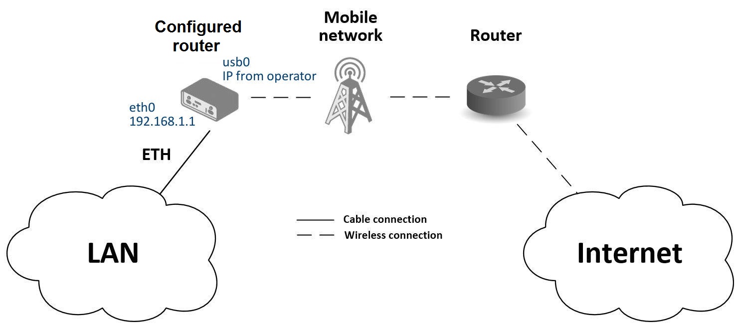
Access to the Internet from LAN
This use case describes how to provide Internet access to a Local Area Network (LAN) using the router's cellular connection. A SIM card with an active data plan from a mobile network operator is required.
Initial Setup
- Insert an active SIM card into the SIM1 slot.
- Attach an appropriate antenna to every antenna connector on the device. For optimal cellular performance, both the main (ANT) and diversity (DIV) antennas are required. If your router includes Wi-Fi or GNSS capabilities, their respective antennas must also be connected.
- Connect your computer or a local network switch to the router's ETH0 port.
- Connect the power supply to power on the router.
After powering on, wait for the router to register on the mobile network. A successful connection is indicated by the WAN and DAT LEDs on the front panel.
Configuration
While factory settings are often sufficient, you can review or modify the configuration in the router's web interface via the Configuration section.
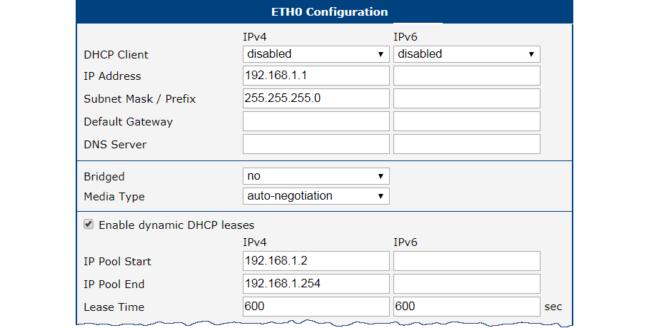
Ethernet Configuration
Navigate to Configuration → Ethernet. The LAN interface (ETH0) is pre-configured with a static IP address of 192.168.1.1. The DHCP server is also enabled by default, automatically assigning IP addresses to connected devices (the first device receives 192.168.1.2, and so on). No changes are needed for this use case.
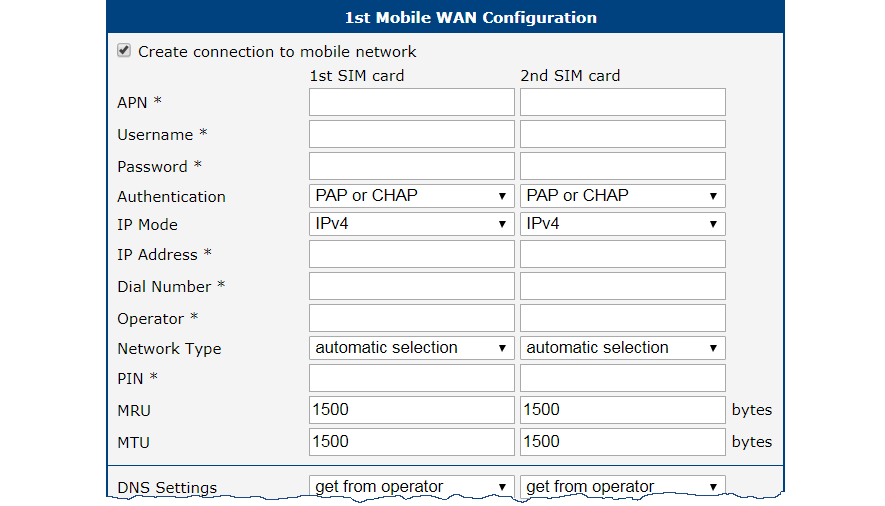
Mobile WAN Configuration
Navigate to Configuration → Mobile WAN. Ensure that the Create connection to mobile network option is enabled (the default setting). For most public SIM cards, you do not need to fill in the APN, username, or password.
Verifying Connectivity
Navigate to Status → Mobile WAN. This page displays key details about the connection, including the operator, signal strength, and a Connection successfully established message. You can also inspect Status → Network to see the new mobile interface (usb0) and the IP address assigned by the operator. Once confirmed, all devices on the LAN have Internet access.
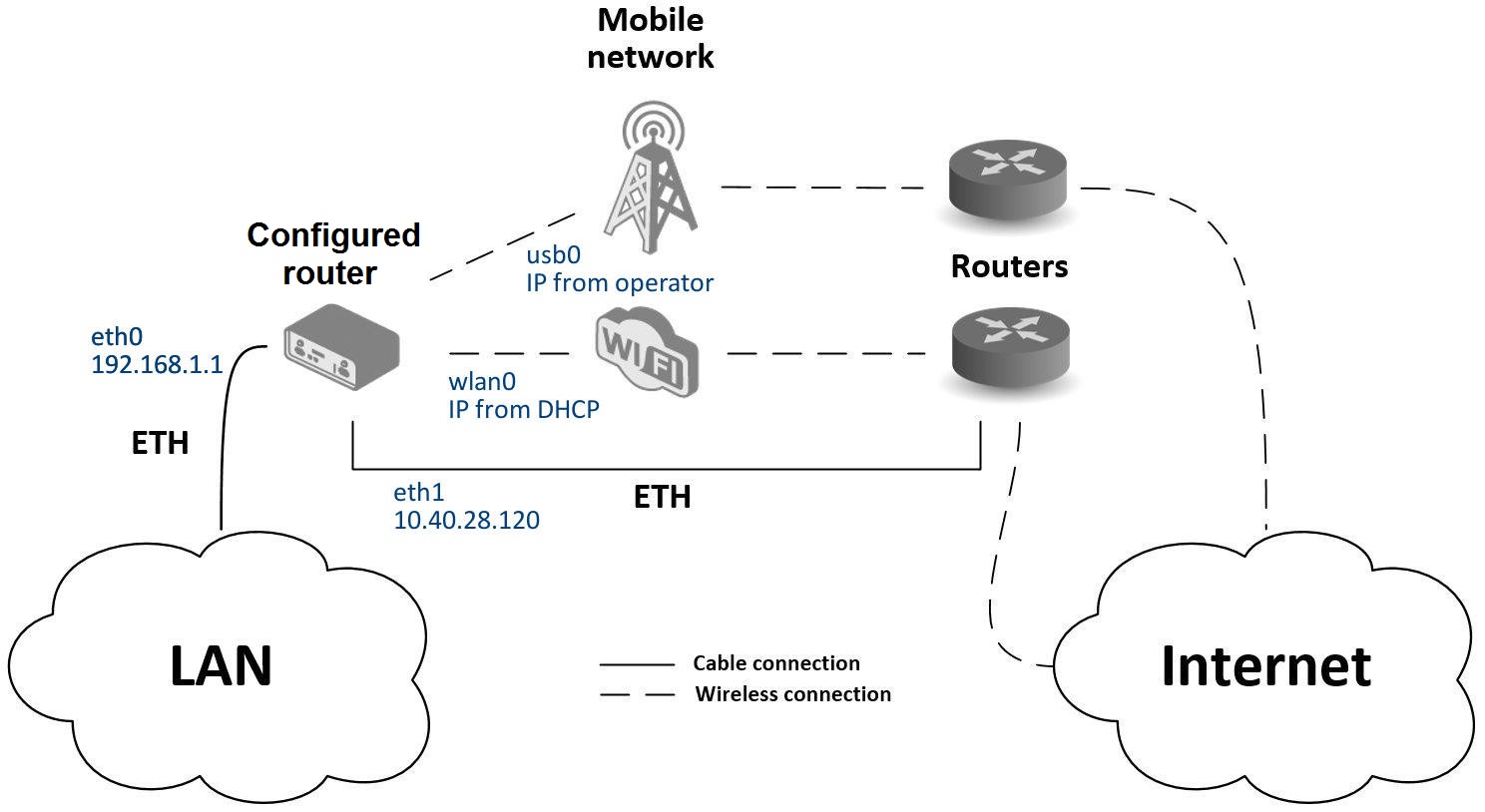
Backup Access to the Internet from LAN
This use case demonstrates how to configure connection redundancy by setting up multiple Internet sources and defining their priority. The router automatically switches to a lower-priority connection if a higher-priority one fails, ensuring continuous Internet access for the LAN via the Backup Routes feature. A typical scenario is LTE failover, where the cellular (Mobile WAN) connection automatically backs up the primary wired or Wi-Fi WAN connection.
Interface Configuration
Configure each interface that will serve as an Internet source. The LAN interface (ETH0) can be left with its default settings.
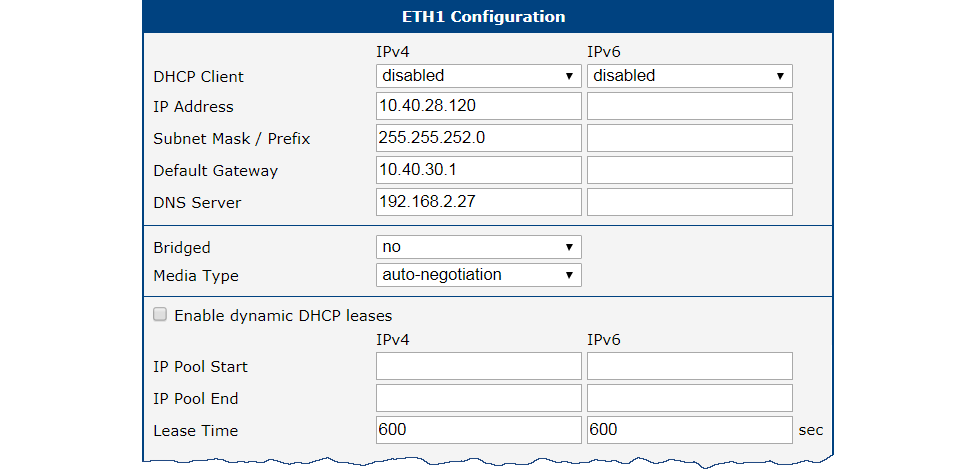
Ethernet WAN Configuration
The ETH1 port is used as the primary wired WAN connection.
- Navigate to Configuration → Ethernet → ETH1.
- Configure the interface with a static IP address, subnet mask, default gateway, and DNS server provided by your Internet Service Provider.
- Click Apply to save the changes.
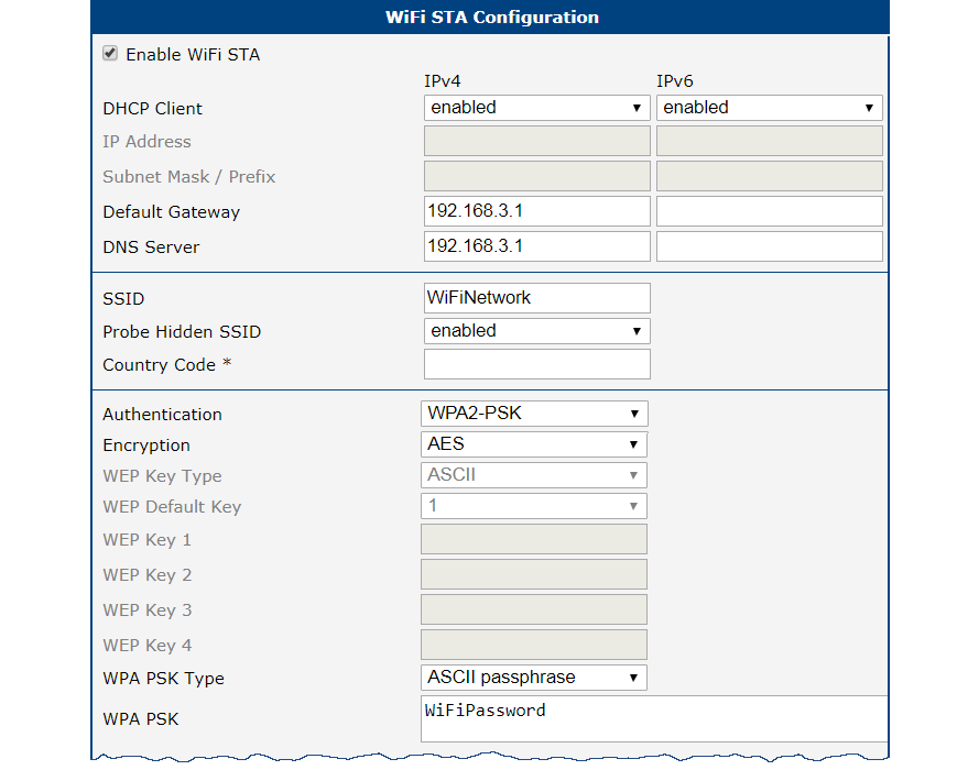
Wi-Fi WAN Configuration
To use Wi-Fi as a backup connection, configure the router as a client (Station) to another Wi-Fi network.
- Navigate to Configuration → WiFi → Station.
- Check Enable WiFi STA.
- If the Wi-Fi network provides settings automatically, enable the DHCP client. Otherwise, manually enter the default gateway and DNS server addresses.
- Enter the network's SSID and select the appropriate Authentication, Encryption, and WPA PSK Type.
- Enter the Wi-Fi password and click Apply.
You can verify the connection in Status → WiFi, where a successful connection shows wpa_state=COMPLETED.
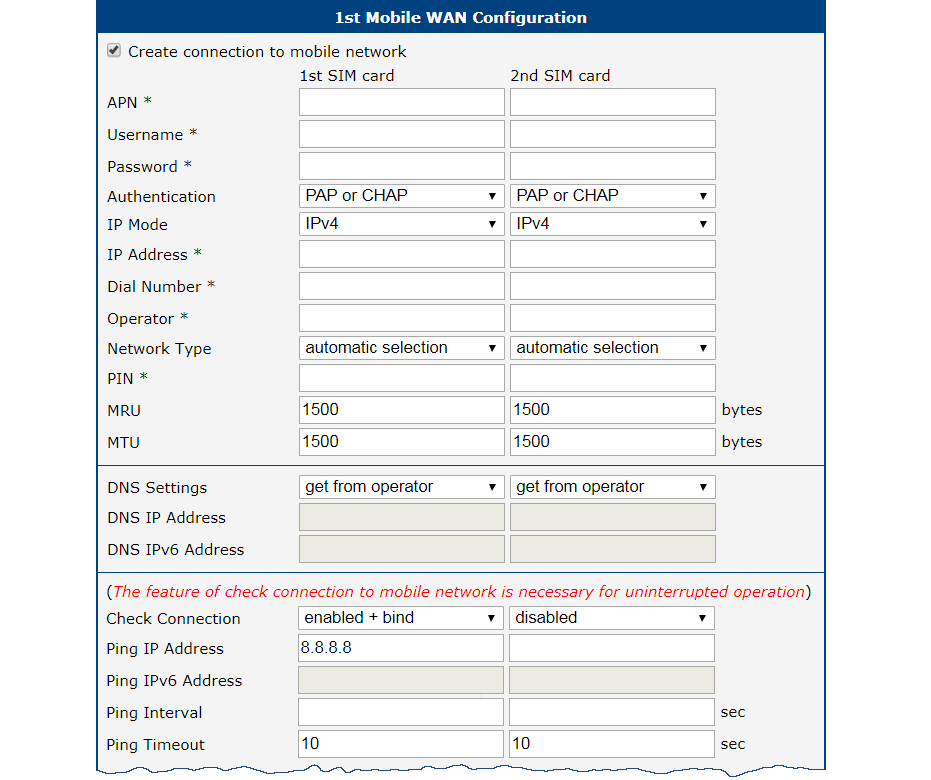
Mobile WAN Configuration
The cellular connection serves as the final backup. Insert an active SIM card into the SIM1 slot and attach the cellular antenna. To integrate it into the backup system:
- Navigate to Configuration → Mobile WAN.
- Set the Check connection option to enabled + bind.
- Enter a reliable IP address to ping (e.g., your operator's DNS server) and set the check interval.
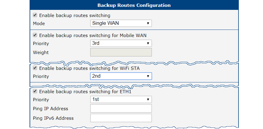
Backup Routes Configuration
After configuring the interfaces, set their priority in Configuration → Backup Routes.
- Set the priority for each WAN interface:
- 1 (Highest):
eth1(Wired Ethernet) - 2 (Medium):
wlan0(Wi-Fi) - 3 (Lowest):
usb0(Cellular)
- 1 (Highest):
- Check Enable backup routes switching for each route.
- Click Apply to save the configuration.
Verifying Failover
Monitor all network interfaces under Status → Network. The route table at the bottom of the page shows which interface is currently active as the default route. If eth1 fails, the default route switches to wlan0. If wlan0 also fails, it switches to usb0.
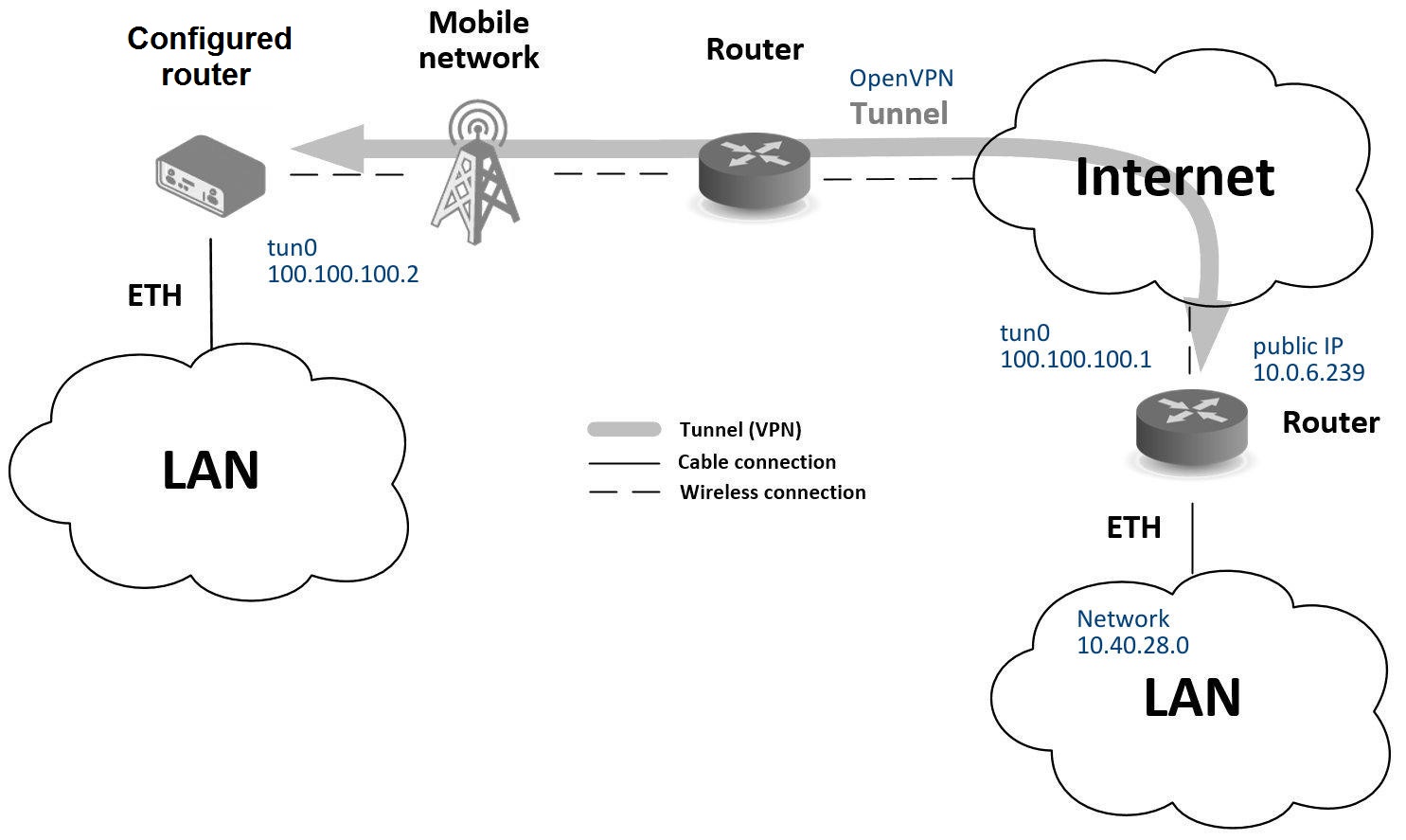
Secure Network Interconnection with VPN
A Virtual Private Network (VPN) creates a secure, encrypted tunnel over an untrusted public network (such as the Internet), allowing two or more separate LANs to communicate as if they were a single private network. This ensures both the confidentiality and integrity of the exchanged data.
Advantech routers support several VPN protocols, including:
- OpenVPN: A highly flexible and secure SSL/TLS-based VPN.
- IPsec: A standards-based framework for securing IP communications.
The router also supports non-encrypted tunneling protocols such as GRE, PPTP, and L2TP, which can be combined with IPsec to create secure VPNs.
This example demonstrates how to establish an OpenVPN tunnel between two routers using a pre-shared secret key for authentication.
Configuration
Mobile WAN Configuration
A stable Internet connection is required before establishing a VPN tunnel. Insert a SIM card and attach the antenna. The router typically establishes a cellular connection automatically. Verify that the mobile connection is active under Configuration → Mobile WAN.
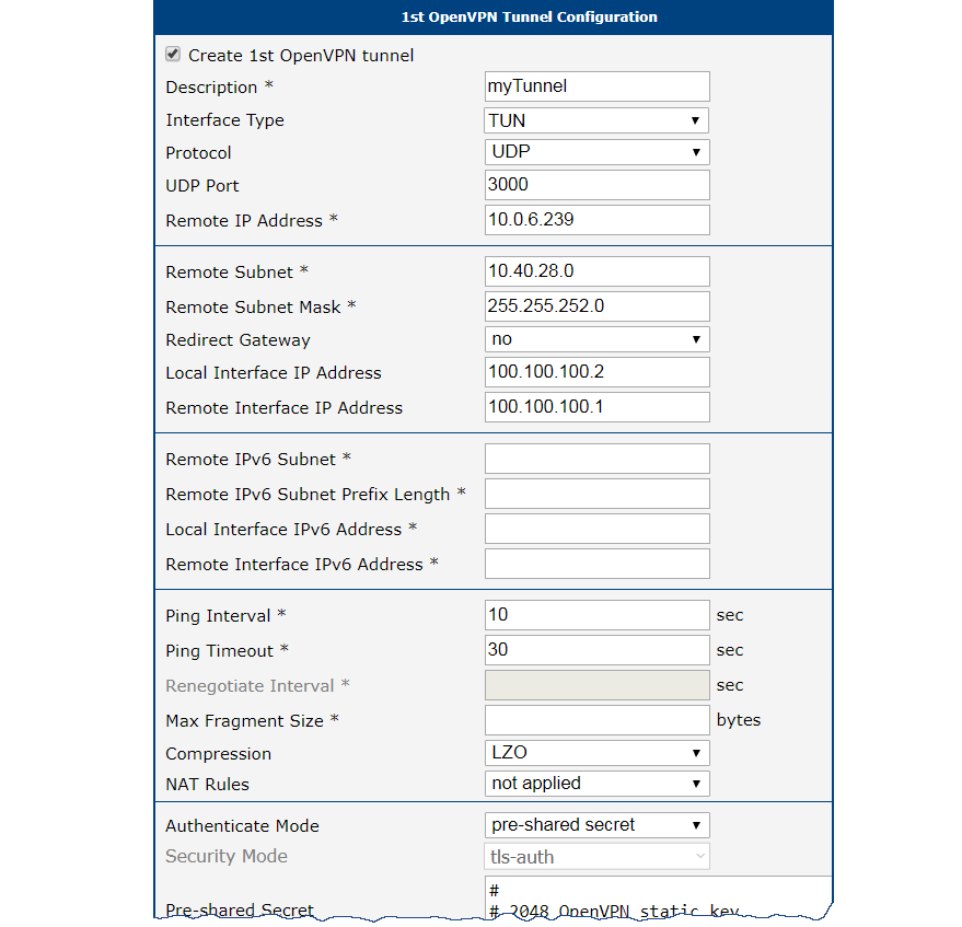
OpenVPN Configuration
- Navigate to Configuration → OpenVPN.
- Enable one of the available tunnels by checking Create 1st OpenVPN tunnel.
- Set the Protocol and Port to match the settings of the remote router.
- In the Remote Host and Port field, enter the public IP address of the remote router.
- In the Authentication Mode dropdown, select Static key (pre-shared).
- Paste the pre-shared secret key into the Static key field.
- Define the virtual IP addresses for the tunnel endpoints in Local Interface IP Address and Remote Interface IP Address. These must form a mini-subnet for the tunnel (e.g.,
10.8.0.1and10.8.0.2). - Click Apply to save the configuration.
Verifying Connectivity
Confirm that the VPN tunnel is active:
- Network Status: Navigate to Status → Network. A new virtual interface
tun0should be listed with the IP address you configured. - System Log: Navigate to Status → System Log. Look for an
Initialization Sequence Completedentry, confirming the OpenVPN tunnel is established.
Once the tunnel is active, you can verify it by pinging the remote tunnel endpoint's IP address from the router's command-line interface via SSH.
Serial Gateway
The Serial Gateway feature encapsulates serial data into IP packets, enabling communication with serial devices (such as PLCs, meters, or sensors) over an IP network. This creates a virtual serial port across the Internet, allowing a central SCADA system or remote PC to collect data from or control legacy serial equipment.
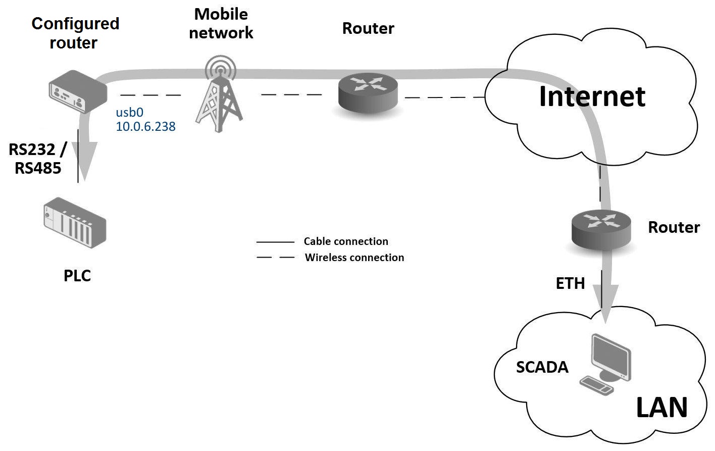
In this example, the router's RS232 port is connected to a PLC, and the router is configured as a TCP server. A remote PC (SCADA) connects as a TCP client to communicate with the PLC.
Configuration
Mobile WAN Configuration
A stable Internet connection is essential. Insert an active SIM card into the SIM1 slot and attach the cellular antenna. The router automatically connects to the mobile network. The public IP address assigned by the mobile operator is used by the remote client to connect to the serial gateway. For more details, see the Mobile WAN section in the Configuration chapter.
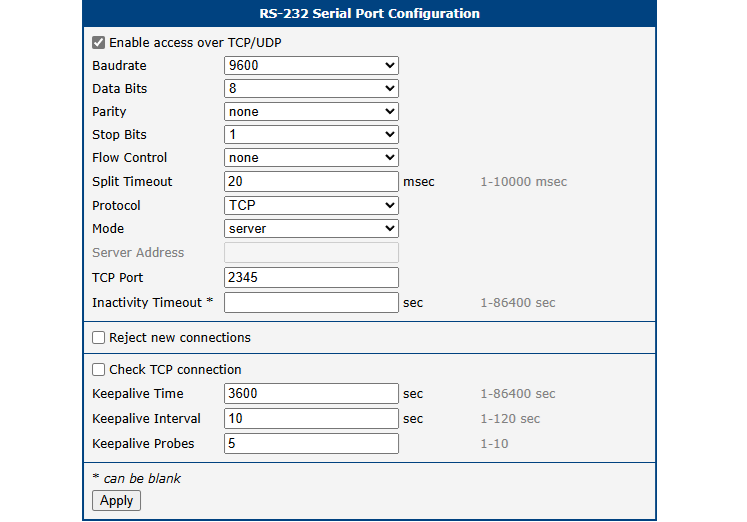
Peripheral Port (RS232) Configuration
- Navigate to Configuration → Peripheral Ports → RS-232.
- Check Enable access over TCP/UDP.
- Set Protocol to
TCP. - Set Mode to
server. The router will listen for incoming connections. - In the TCP Port field, enter the port number on which the router will listen (e.g.,
2345). - Configure the serial communication parameters (Baud Rate, Data Bits, Parity, etc.) to match the connected serial device.
- Click Apply to save the configuration.
Verifying Connectivity
The remote PC (SCADA) can establish a TCP connection to the router's public IP address (e.g., 10.0.6.238) on the configured port (e.g., 2345). All data sent over this TCP session is forwarded to the PLC via the serial port, and vice versa.
Monitor the connection status in Status → System Log. When the remote client connects successfully, a TCP connection established message appears in the log.