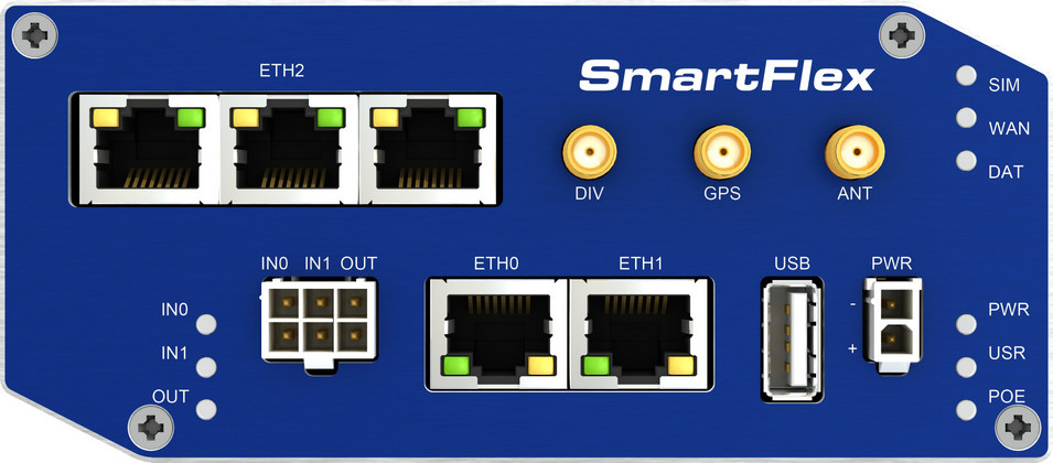
Hardware and Connectivity
Refer to the Hardware Components section for a detailed summary of the product's hardware.
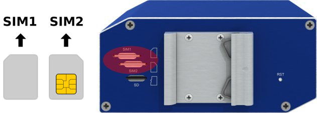
SIM Card Slots
The router includes two slots for Mini SIM cards (2FF; 25.0 x 15.0 x 0.76 mm), located on the rear panel. If the router is used for cellular communication, insert an activated SIM card with an unblocked PIN code. Each SIM card can be configured with a unique Access Point Name (APN).
Changing the SIM Card
- Always disconnect the router from the power supply before handling the SIM card.
- To remove a SIM card, press the card slightly into its slot until you hear a click. Release it to eject.
- Insert the new SIM card into the slot until it clicks into place.
microSD Card
The microSD card slot is located on the rear panel. The router supports SDHC cards up to 32 GB and SDXC cards from 32 GB to 64 GB. Supported file systems are vfat, ext2, ext3, and ext4.
After inserting a microSD card, verify detection using dmesg | grep mmc. Mount the card with:
mount /dev/mmcblk0p1 /mnt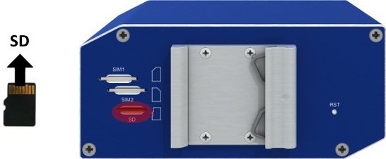
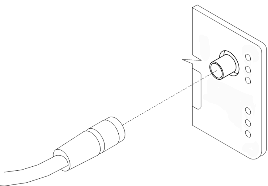
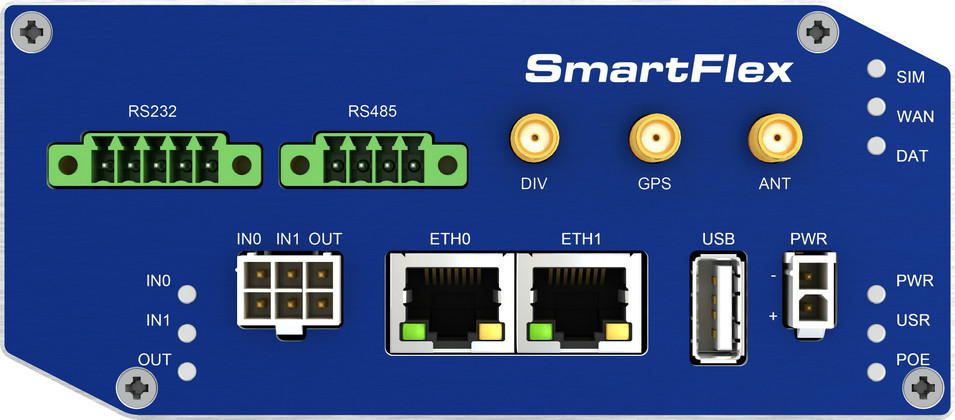
Antenna Connections
The ANT and DIV connectors are SMA connectors on the front panel. Connect the main cellular antenna to the ANT connector and the diversity antenna to the DIV connector. The GPS connector is an SMA connector for a GNSS antenna; the router supplies power to active GPS antennas. An RP-SMA connector labeled Wi-Fi is available on versions equipped with a Wi-Fi module.
Warning
- The router cannot operate without a main antenna connected to the ANT connector.
- Connect the diversity antenna to the DIV connector for optimal MIMO DL performance.
- Ensure a tightening torque of 0.9 Nm when attaching antennas.
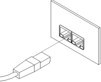
Ethernet Interfaces
The router features two Ethernet interfaces (ETH0 and ETH1) accessible via RJ45 panel sockets. The pinout is as follows:
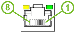
| Pin | 10BASE-T & 100BASE-T | PoE (Mode B) |
|---|---|---|
| 1 | Tx+ (Transmit Data+) | — |
| 2 | Tx- (Transmit Data-) | — |
| 3 | Rx+ (Receive Data+) | — |
| 4 | — | PoE+ (positive pole) |
| 5 | — | PoE+ (positive pole) |
| 6 | Rx- (Receive Data-) | — |
| 7 | — | PoE− (negative pole) |
| 8 | — | PoE− (negative pole) |
The insulation strength of the Ethernet ports depends on the router version:
| Router Version | Insulation from Router | Insulation between Ports |
|---|---|---|
| Without PoE | 1.5 kV | 1.5 kV |
| PoE PD | 1.5 kV | None |
| PoE PSE | None | None |
Power over Ethernet
Tips
- Available only on models with the PoE feature (see order codes).
- On SWITCH versions, PoE PD is available on ETH0 and ETH1 only — the ETH2 ports cannot power the router.
- The IEEE 802.3af/PoE (Type 1) and IEEE 802.3at/PoE+ (Type 2) standards are supported. The router is Mode B compliant.
- Use the
psecommand to control PoE PSE. Refer to the Command Line Interface application note.
Warning
The power supply for a PoE-equipped router must be 24–60 V DC for the router to start correctly.
PoE PD
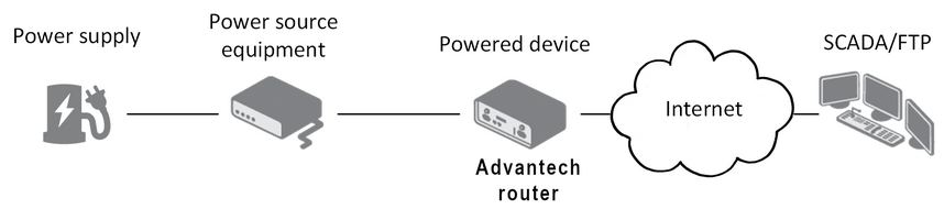
The POE LED lights up green when PoE power is available on an ETH port. If the PWR connector is also used and the supply voltage exceeds 15 V DC, the router is powered from the PWR connector. If the PWR voltage is below 15 V DC and PoE is available, the router draws power from the ETH port via PoE.
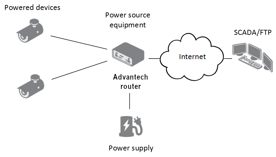
PoE PSE
Warning
The power supply for a PoE PSE router must provide 44–57 V DC and at least 65 W to support full PoE+ (Class 4) on both ETH ports.
The PoE PSE state is shown by the POE LED: steady green indicates sufficient voltage; blinking green indicates the router is powering a device via an ETH port; yellow indicates insufficient voltage or power; yellow blinking indicates the powered device is drawing too much power. You can enable or disable PoE PSE separately for ETH0 and ETH1 in the web interface under LAN → Primary or Secondary.
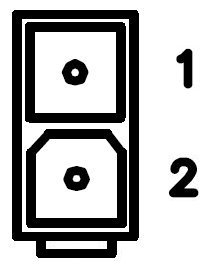
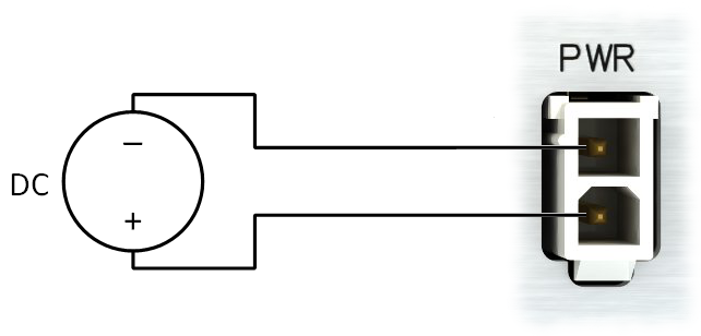
Power Supply
The router is powered through a 2-pin panel socket. The pinout is as follows:
| Pin | Signal Mark | Description |
|---|---|---|
| 1 | GND(−) | Negative pole of DC supply voltage |
| 2 | VCC(+) | Positive pole of DC supply voltage |
Warning
The router must be powered by a supply classified as a Limited Power Source (LPS) according to Annex Q of IEC 62368-1. If the provided power cable is not used, use cables with a minimum wire cross-section of 0.5 mm².
For power supply parameters, refer to the Technical Parameters chapter. The router includes protection against reversed polarity without signaling.
Warning
Grounding the negative pole disables the reversed polarity protection.
Low Power Mode (LPM)
Warning
In applications requiring low power consumption, such as solar power (not 24/7 operation), use LPM before powering down the entire router.
LPM minimizes power consumption by placing the router in a sleep state. Activate LPM using the lpm command. Wake the router from LPM using the BIN1 input or after a preset duration. Refer to the Command Line Interface application note for detailed instructions.
Grounding
Tips
All metal parts are connected together with the negative pole of the power supply (common pole).
USB Port
The USB-A 2.0 connector is located on the front panel. The port includes overload protection; if the protection activates, reboot the router to re-enable the port.

After inserting a USB storage device, verify detection using dmesg | grep usb. Mount the device with:
mount /dev/sda1 /mntI/O Port
The I/O interface is accessible via a 6-pin panel socket. The pinout is as follows:
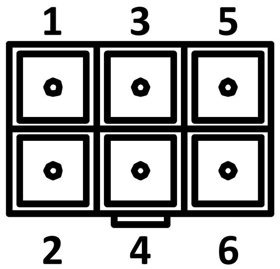
| Pin | Signal Mark | Description |
|---|---|---|
| 1 | IN0 | Digital input 0 |
| 2 | IN0 | Digital input 0 |
| 3 | IN1 | Digital input 1 |
| 4 | IN1 | Digital input 1 |
| 5 | OUT | Digital output |
| 6 | OUT | Digital output |
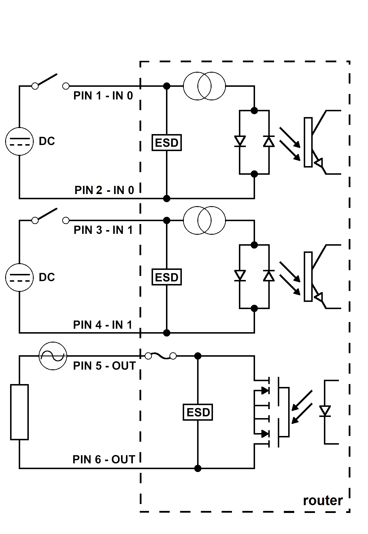
The I/O interface supports digital input processing and digital output control. Digital output is open in the default configuration. The isolation strength is 1.5 kV; pins are isolated from each other with the same strength. The input circuits are bipolar and allow connection with either a common positive or common negative reference.
Digital Inputs
| Threshold | Voltage | Current | Web Interface Status |
|---|---|---|---|
| Logic 1 max | 3 V | 0.4 mA | Off |
| Logic 0 min | 5 V | 0.7 mA | On |
| Logic 0 typical | 12 V | 2 mA | On |
| Logic 0 max | 60 V | 7 mA | On |
Check the digital input status in the shell using the io get bin0 or io get bin1 command.
Digital Output
The digital output supports up to 60 V AC/DC at 300 mA. The output current is limited by a resettable fuse (300 mA).
LED Indicators
The front panel includes status LEDs. Each ETH port has two additional LEDs.
| Caption | Color | State | Description |
|---|---|---|---|
| PWR | Green | On | Starting the router. |
| Blinking | Router is ready. | ||
| Fast blinking | Updating firmware. | ||
| USR | Yellow | — | Controlled by the user. |
| POE | Yellow | On | PSE mode: Insufficient voltage on the PWR connector. |
| Blinking | PSE mode: The powered device is drawing too much power.¹ | ||
| Green | On | PD mode: PoE power detected on an ETH port. PSE mode: Correct power supply on the PWR connector. | |
| Blinking | PSE mode: The router is powering a device via an ETH port. | ||
| Off | PD mode: No power supply on the ETH port. PSE mode: PoE is disabled. | ||
| SIM | Green | On | The first SIM card is active. |
| Yellow | On | The second SIM card is active. | |
| WAN | Yellow | Fades out 1× per 5 s | Signal strength is good. |
| Fades out 1× per 2 s | Signal strength is fair.² | ||
| Fades out 1× per 1 s | Signal strength is poor.³ | ||
| DAT | Red | Blinking | Cellular communication is in progress. |
| IN0 | Green | On | The first digital input is active. |
| IN1 | Green | On | The second digital input is active. |
| OUT | Yellow | On | The digital output is active. |
| ETH0 / ETH1 | Green | On | 100 Mbps selected. |
| Off | 10 Mbps selected. | ||
| Yellow | On | The network cable is connected. | |
| Blinking | Data transmission. | ||
| Off | The network cable is not connected. |
¹ Can also indicate a device without PoE support connected on the other end of the cable — caused by the device's low input impedance (below 500 Ω). To resolve, disable PoE PSE on the relevant ETH port in the web interface.
² Or if the difference between neighboring cells is exactly 3 dBm.
³ Or if the difference between neighboring cells is less than 3 dBm.
Tips
The WAN LED status is updated every 10 seconds.
Reset Options
The RST button is located on the rear panel and has multiple functions. For details, refer to Initial Configuration → Reset.
Tips
Use a narrow screwdriver or a small tool to press the RST button.
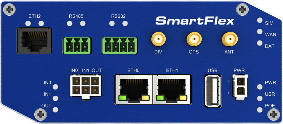
Hardware Interfaces
The SmartFlex router is available in versions with one of the following optional interface boards:
- SWITCH interface
- RS232-RS485/422 interface
- RS232-RS485-ETH interface
SWITCH Interface
The three LAN ports of the SWITCH interface (RJ45 connectors) act as a switch: the router reads Ethernet frames from any port and transmits them on the other ports. Each port transmits frames independently.
Tips
Router versions with the SWITCH interface have a lower maximum operating temperature of +70 °C.
State indication:
| Color | State | Description |
|---|---|---|
| Green | On | 100 Mbps selected. |
| Green | Off | 10 Mbps selected. |
| Yellow | On | The network cable is connected. |
| Yellow | Blinking | Data transmission. |
| Yellow | Off | The network cable is not connected. |
Technical specification:
| Parameter | Value |
|---|---|
| Maximum data rate | 100 Mbps |
| Maximum cable length | 100 m |
RS232-RS485/422 Interface
This interface uses a 5-pin terminal block connector for RS232 and a 4-pin terminal block connector for RS485/422. The insulation strength is 2.5 kV. The RS232 and RS485/422 connectors share a common ground and are not isolated from each other.
Warning
When connecting terminal block connectors, use cables with a cross-section of 0.2–1.0 mm² (30–16 AWG). Recommended stripping length is 5 mm. Tighten M2 captive screws with 0.3 Nm torque using a 0.5 × 3 mm screwdriver.
RS232 connector (5-pin):

| Pin | Signal Mark | Description |
|---|---|---|
| 1 | CTS | Clear To Send |
| 2 | RTS | Request To Send |
| 3 | GND | Signal ground (shared with the RS485/422 connector) |
| 4 | RXD | Receive Data |
| 5 | TXD | Transmit Data |
RS485 connector (4-pin):

| Pin | Signal Mark | Description |
|---|---|---|
| 1 | TxRx+ | RS485 B (+) |
| 2 | TxRx− | RS485 A (−) |
| 3 | TxRx+ | RS485 B (+) |
| 4 | TxRx− | RS485 A (−) |
Each signal uses two parallel terminals for increased connection flexibility. The same 4-pin connector supports RS422 mode:
| Pin | Signal Mark | Description |
|---|---|---|
| 1 | RxD+ | RS422 (+) |
| 2 | RxD− | RS422 (−) |
| 3 | TxD+ | RS422 (+) |
| 4 | TxD− | RS422 (−) |
Select RS485 or RS422 mode using jumpers on the board: three jumpers for RS485, one jumper for RS422. The default configuration is RS485 with termination off. Activate the termination resistor using a jumper on the port board.
Warning
Only the Advantech service center can perform jumper configuration inside the router.
Technical specification:
| Parameter | Value |
|---|---|
| Maximum RS232 bus current | 15 mA |
| Maximum devices on RS485 bus | 32 |
| Maximum RS485 output current | 60 mA |
| Maximum data rate | 230400 bps (RS232 and RS485) |
| Maximum cable length | RS232 20 m, RS485 1200 m |
RS232-RS485-ETH Interface
This interface board includes a panel RJ45 connector (ETH2) and terminal block connectors for RS485 (3-pin) and RS232 (4-pin). The insulation strength between the ETH2 and RS485 interfaces and the rest of the router is 2.5 kV. The RS232 interface is not isolated from the rest of the router.
Warning
When connecting terminal block connectors, use cables with a cross-section of 0.2–1.0 mm² (30–16 AWG). Recommended stripping length is 5 mm. Tighten M2 captive screws with 0.3 Nm torque using a 0.5 × 3 mm screwdriver.
ETH2 connector:
| Pin | Signal Mark | Description |
|---|---|---|
| 1 | TXD+ | Transmit Data — positive pole |
| 2 | TXD− | Transmit Data — negative pole |
| 3 | RXD+ | Receive Data — positive pole |
| 4 | — | — |
| 5 | — | — |
| 6 | RXD− | Receive Data — negative pole |
| 7 | — | — |
| 8 | — | — |
RS485 connector (3-pin):
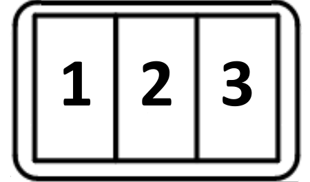
| Pin | Signal Mark | Description |
|---|---|---|
| 1 | GND | Signal ground (isolated from the router's ground) |
| 2 | TxRx+ | RS485 B (+) |
| 3 | TxRx− | RS485 A (−) |
Activate the termination resistor using a jumper on the port board.
RS232 connector (4-pin):
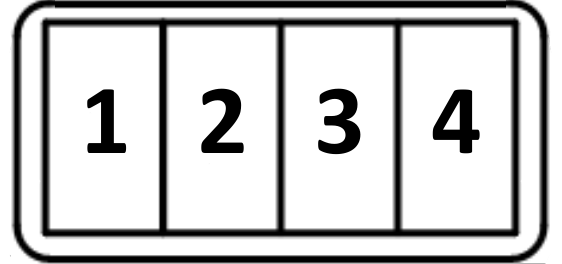
| Pin | Signal Mark | Description |
|---|---|---|
| 1 | AUX | +5 V / 500 mA |
| 2 | GND | Signal ground (common with the router's signal ground) |
| 3 | RXD | Receive Data |
| 4 | TXD | Transmit Data |
State indication:
| Connector | Color | State | Description |
|---|---|---|---|
| ETH2 | Green | On | 100 Mbps selected. |
| Off | 10 Mbps selected. | ||
| Yellow | On | The network cable is connected. | |
| Blinking | Data transmission. | ||
| Off | The network cable is not connected. | ||
| RS485 / RS232 | Green | — | Indicates receive data. |
| Yellow | — | Indicates transmit data. |
Technical specification:
| Parameter | Value |
|---|---|
| Maximum RS232 bus current | 15 mA |
| Maximum devices on RS485 bus | 32 |
| Maximum RS485 output current | 60 mA |
| Maximum data rate | 230400 bps (RS232), 230400 bps (RS485), 100 Mbps (ETH2) |
| Maximum cable length | RS232 20 m, RS485 1200 m, ETH2 100 m |