Hardware and Connectivity
Refer to the Hardware Components section for a detailed summary of the product's hardware.
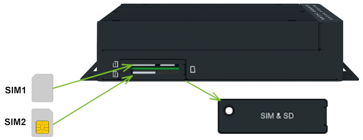
SIM Card Slots
Tips
This section applies to cellular models only. The ICR-4401 (LAN router) does not include SIM card slots.
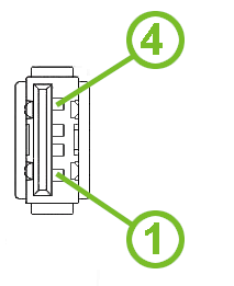
The router has two SIM card slots located on the rear panel under a metal cover. To communicate over a cellular network, insert an activated, data-provisioned SIM card into a SIM card slot. You can install two SIM cards simultaneously to use the SIM switching feature. You can configure each SIM card with a different APN (Access Point Name).
Tips
SIM card type: Mini SIM (2FF) — 25.0 × 15.0 × 0.76 mm.
Changing the SIM Card
- Always disconnect the router from the power supply before handling the SIM card.
- Unscrew the SIM card cover screw on the rear panel and remove the cover.
- To remove an inserted SIM card, use the flat end of a spudger or your fingernail. Press the card slightly into its slot until you hear a click. Release the card; it will pop out of its slot.
- To insert a SIM card, push the card into the slot until it clicks into place.
- Replace the cover and tighten the screw.
If the SIM card requires a PIN, enter it in the router's web interface under Administration → Unlock SIM Card.
Antenna Connections
The antenna connectors available depend on the router model:
- ICR-4401 (LAN router): Three RP-SMA female connectors (WIFI1) for Wi-Fi antennas.
- ICR-44xx (cellular, 2×2 MIMO): Two SMA female connectors — ANT (main) and DIV (diversity) — for cellular antennas, a dedicated GNSS SMA connector for the GNSS antenna, and RP-SMA connectors (WIFI1) for Wi-Fi antennas.
- ICR-4453, ICR-4461, ICR-4471-CS (5G/multi-band cellular): Four SMA female connectors (ANT0, ANT1, ANT2, ANT3) for cellular antennas, plus WIFI1 RP-SMA connectors for Wi-Fi. On the ICR-4461, the GNSS antenna connectors are shared with the cellular connectors: ANT3 for the L1 band and ANT1 for the L5 band. The ICR-4453 and ICR-4471-CS use a dedicated GNSS connector.
Warning
Always operate the router with a cellular antenna securely connected to the cellular antenna connector. Transmitting without an antenna attached causes RF energy to be reflected at the open connector, which can permanently damage the radio circuitry. Ensure the antenna is properly installed before powering on or transmitting.
Tips
The recommended tightening torque for the antenna SMA connectors is 0.9 Nm.
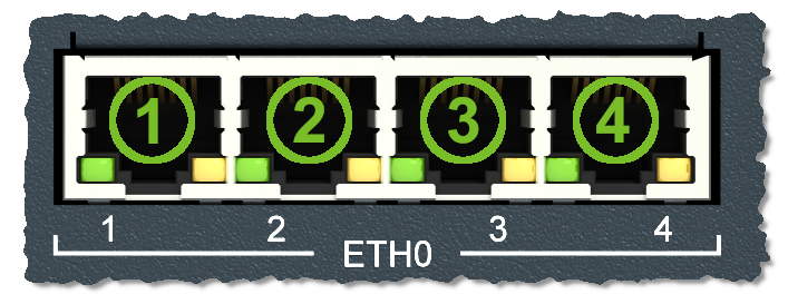
Ethernet Interfaces
The router provides four switched ETH0 ports and one ETH1 Gigabit Ethernet interface, all accessible via RJ45 panel sockets. When viewed from the front, the first ETH0 port is on the left.
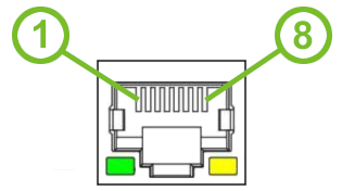
| Pin | 10BASE-T & 100BASE-T | 1000BASE-T | PoE PSE (Mode B) |
|---|---|---|---|
| 1 | Tx+ (Transmit Data+) | BI_DA+ (BiDirectional pair A+) | — |
| 2 | Tx- (Transmit Data-) | BI_DA- (BiDirectional pair A-) | — |
| 3 | Rx+ (Receive Data+) | BI_DB+ (BiDirectional pair B+) | — |
| 4 | — | BI_DC+ (BiDirectional pair C+) | PoE PSE+ (positive pole) |
| 5 | — | BI_DC- (BiDirectional pair C-) | PoE PSE+ (positive pole) |
| 6 | Rx- (Receive Data-) | BI_DB- (BiDirectional pair B−) | — |
| 7 | — | BI_DD+ (BiDirectional pair D+) | PoE PSE- (negative pole) |
| 8 | — | BI_DD- (BiDirectional pair D-) | PoE PSE- (negative pole) |
Tips
- All four ETH0 ports support PoE PSE on models equipped with this feature. See Power over Ethernet (PoE PSE).
- The isolation barrier of the Ethernet ports from ground is 1500 V.
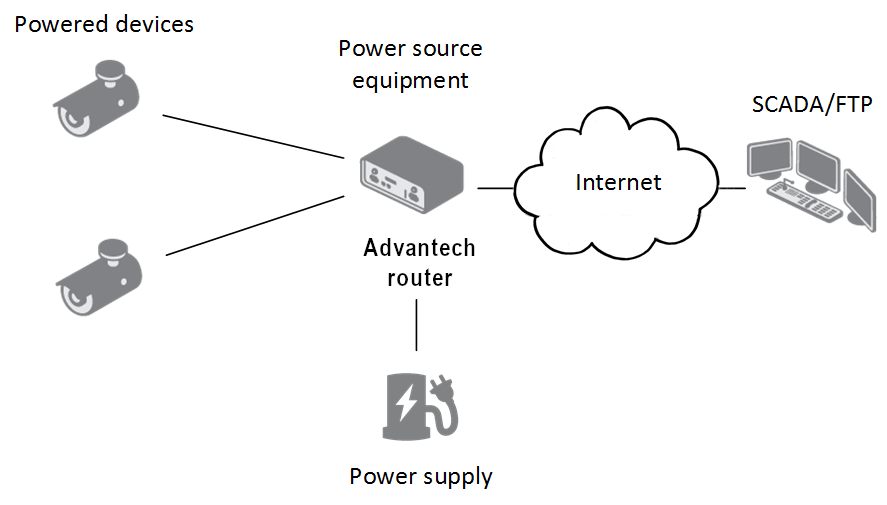
Power over Ethernet (PoE PSE)
Tips
- Available only on models with the PoE PSE feature.
- The router supports IEEE 802.3af/PoE (Type 1) and IEEE 802.3at/PoE+ (Type 2), Mode B.
- Use the
psecommand to manage PoE. Refer to the Command Line Interface application note.
Warning
The router's power supply must be 48 V DC for the router to operate as a PoE PSE device.
The PoE PSE feature enables the router to power other devices over Ethernet. All four ETH0 ports support PoE PSE; enable each port individually from the Ethernet configuration pages. Monitor the PoE status (current, voltage, power, and power class) on the General status page.
| Parameter | Value |
|---|---|
| Required power supply | 48 V / up to 135 W |
| Power available to a PoE device | 12.95 W per port |
| Required power supply per PoE device | 15.40 W per port |
| Power available to a PoE+ device | 25.50 W per port |
| Required power supply per PoE+ device | 30.0 W per port |
Power Budget Examples:
Example 1: Using the Advantech RPS-ICR4-WR2-PSE power supply (65 W; assuming 15 W for the router itself):
- Up to three PoE devices (3 × 15.4 W + 15 W = 61.2 W < 65 W)
- Or one PoE+ device (1 × 30 W + 15 W = 45 W < 65 W)
Example 2: To power four PoE+ devices, use a power supply rated at least 135 W (4 × 30 W + 15 W = 135 W).
Warning
Ensure the power supply can cover the power requirements of all connected PoE devices plus the router itself. Use a power supply with some power reserve.
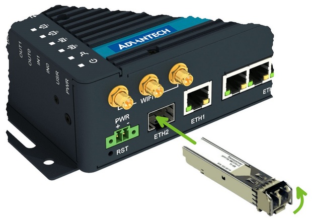
SFP Cage (ETH2)
The ETH2 port is an SFP cage that accepts a hot-pluggable SFP or SFP+ module with speeds up to 10 Gbps.
Installing an SFP Module:
- If the SFP module has a bale clasp, ensure it is closed before inserting.
- Hold the module with the hardware label facing up.
- Gently insert the module into the ETH2 slot and push until it snaps into place.
The following SFP modules have been successfully tested:
| Model | Manufacturer |
|---|---|
| SFP-GSM-20K | Advantech |
| ML-S+31Dout-10 | MaxLink |
| S-3553LC20D | MikroTik |
| SFP-PLUS-LR10-HPE | Hewlett Packard |
| SFP-TXCIS | OEM |
| TXM431-LR(UN) | TP-Link |
| UF-RJ45-1G | Ubiquiti |
Power Supply
A two-pin terminal connector (pitch 3.5 mm) is used to power the router. The matching connector is included as a standard accessory.
| Pin | Signal | Description |
|---|---|---|
| 1 | VCC(+) | Positive pole of DC supply voltage (+9 to +48 V DC) |
| 2 | GND(−) | Negative pole of DC supply voltage |

The required supply voltage is +9 to +48 V DC. The router includes built-in protection against reversed polarity without signaling.
Warning
- Grounding the router using the grounding screw eliminates the protection against reversed polarity. Ensure the negative pole of the DC supply shares the same voltage reference as the grounding screw. A voltage difference between these points may damage the router; only an authorized service center can perform repairs.
- The PoE PSE router version requires 48 V DC to function as a PoE PSE device.
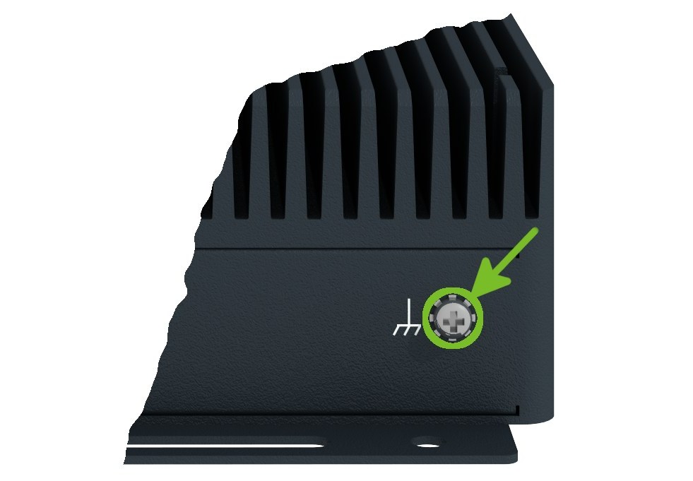
All metal parts, including the chassis, are connected to the negative pole of the power supply (common pole). To protect the router, ground it using the grounding screw as shown below. The maximum tightening torque for the grounding screw is 1 Nm.
Low Power Mode
Warning
In applications requiring low power consumption, such as solar-powered installations not operating 24/7, use Low Power Mode (LPM) before shutting down the entire router.
LPM (Low Power Mode) is a sleep state with minimal power consumption. The router wakes from LPM when the BIN1 input receives a signal or after a predefined period. To enter LPM, use the lpm command. Refer to the Command Line Interface application note for details.
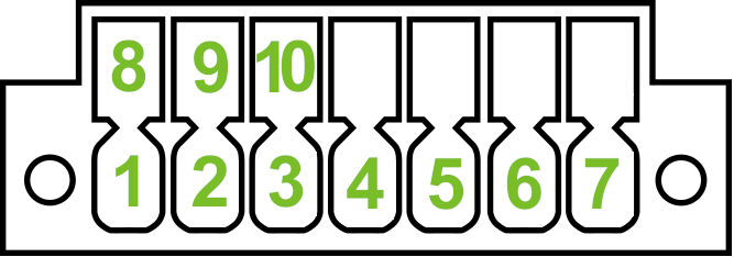
Serial and I/O Port
The RS232, CAN, RS485, and digital I/O interfaces all share a single 14-pin terminal block panel socket. None of these interfaces are isolated from the router.
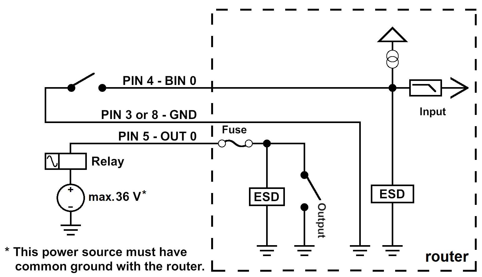
I/O Port
The I/O interface provides two digital inputs and two digital outputs on pins 11–14.

| Pin | Signal | Description |
|---|---|---|
| 11 | BIN0 | First digital input |
| 12 | BOUT0 | First digital output |
| 13 | BIN1 | Second digital input |
| 14 | BOUT1 | Second digital output |
RS232 Interface
| Pin | Signal | Description |
|---|---|---|
| 1 | RXD | Received Data |
| 2 | CTS | Clear to Send |
| 3 | GND | Ground |
| 4 | RTS | Request to Send |
| 5 | TXD | Transmit Data |
CAN Bus Interface
| Pin | Signal | Description |
|---|---|---|
| 6 | CAN_H | CAN High |
| 7 | CAN_L | CAN Low |
RS485 Interface
| Pin | Signal | Description |
|---|---|---|
| 8 | B (+) | In/Out |
| 9 | A (−) | In/Out |
| 10 | GND | Ground |
USB Port
The router has a single USB 2.0 host port with a USB Type-A socket.
| Pin | Signal | Description | Direction |
|---|---|---|---|
| 1 | +5 V | Positive pole of 5 V DC supply voltage, 0.5 A | — |
| 2 | USB Data− | USB data signal (negative pole) | Input/Output |
| 3 | USB Data+ | USB data signal (positive pole) | Input/Output |
| 4 | GND | Negative pole of DC supply voltage | — |
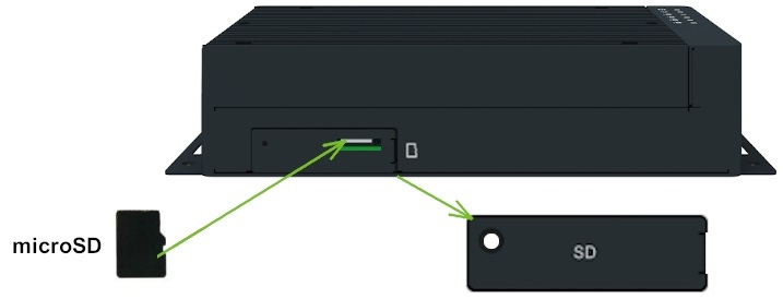
microSD Card
The microSD card reader is located under the SIM cover on the router.
| Specification | Value |
|---|---|
| Supported technologies | SD, SDHC, and SDXC |
| SDHC capacity | Up to 32 GB |
| SDXC capacity | 32 GB to 512 GB |
| Supported filesystems | vfat, ext2, ext3, and ext4 |
Inserting the microSD Card
- To remove an inserted microSD card, use the flat end of a spudger or your fingernail. Press the card slightly into its slot until you hear a click. Release the card; it will pop out of its slot.
- To insert a microSD card, push the card into the slot with the correct orientation as shown until it clicks into place.
Mounting the microSD Card
To access the microSD card in the router's system, mount it:
- Run
dmesgto view recently connected devices and identify the microSD card entry, for example:mmcblk0: p1. - Mount the card to the
/mntdirectory:
mount /dev/mmcblk0p1 /mntTips
For commands to create, mount, check, and unmount a filesystem on a microSD card, refer to the Ext4 Filesystem Utilities router app application note.
LED Indicators
Status LEDs are located on the top side of the router. The ETH0 and ETH1 connectors on the front panel each have two additional LEDs showing the port status.
Tips
The DAT, SIG, TECH, SIM1, and SIM2 LEDs are not present on the ICR-4401 (LAN router).
| Symbol | Caption | Color | State | Description |
|---|---|---|---|---|
| PWR | Green | On | The router is starting up. | |
| Green | Blinking | The router is ready (heartbeat). | ||
| Green | Fast blinking | The router firmware is being updated. | ||
| USR | Green | — | The function of this LED is user-defined. | |
| IN0 | Green | On | The first digital input is active. | |
| IN1 | Green | On | The second digital input is active. | |
| OUT0 | Green | On | The first digital output is active. | |
| OUT1 | Green | On | The second digital output is active. | |
| DAT¹ | Green | Blinking | Cellular communication is in progress. | |
| SIG¹ | Green | On | Good cellular signal. | |
| Orange | On | Fair cellular signal. | ||
| Red | On | Poor cellular signal. | ||
| TECH¹ | Green | On | The active SIM uses 5G technology (4G on non-5G models).² | |
| Orange | On | The active SIM uses 4G technology (3G on non-5G models). | ||
| Red | On | The active SIM uses 3G technology (5G models only).² | ||
| SIM1¹ | Green | On | SIM1 is active for the cellular connection. | |
| Red | Fast blinking | A SIM1 issue (missing card or PIN not entered). | ||
| SIM2¹ | Green | On | SIM2 is active for the cellular connection. | |
| Red | Fast blinking | A SIM2 issue (missing card or PIN not entered). | ||
| ETH0, ETH1 | Green | On | 1 Gbps link. | |
| Green | Off | 100/10 Mbps link. | ||
| Yellow | On | Network cable connected. | ||
| Yellow | Brief off blinks | Data transmission. | ||
| Yellow | Off | Network cable not connected. |
¹ Not present on the ICR-4401 (LAN router).
² On 5G-capable models (ICR-4453, ICR-4461, ICR-4471-CS): Green = 5G, Orange = 4G, Red = 3G. On other cellular models (e.g., ICR-4434): Green = 4G, Orange = 3G; Red is not used.
Reset Options
The RST button is located in a small opening on the router panel and has multiple functions. For details, refer to Initial Configuration → Reset.
Tips
Use a narrow screwdriver to press the RST button.