Hardware and Connectivity
Refer to the Hardware Components section for a detailed summary of the product's hardware.
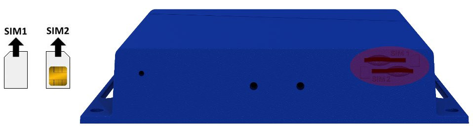
SIM Card Slots
The SmartStart SL305 includes two slots for Mini SIM cards (2FF; 25.0 x 15.0 x 0.76 mm), located on the rear panel. If the router is used for cellular communication, insert an activated SIM card with an unblocked PIN code. Each SIM card can be configured with a unique Access Point Name (APN).
Changing the SIM Card
- Always disconnect the router from the power supply before handling the SIM card.
- To remove a SIM card, use the flat end of a spudger or your fingernail to press the card slightly into its slot until you hear a click. Release it to eject.
- Insert the new SIM card into the slot until it clicks into place.
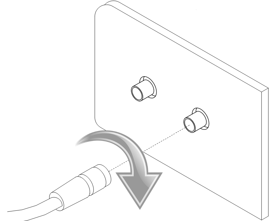
Antenna Connections
The ANT and DIV connectors are SMA connectors located on the front panel. Connect the main cellular antenna to the ANT connector and the diversity antenna to the DIV connector. An RP-SMA connector labeled Wi-Fi is available on versions equipped with a Wi-Fi module.
Warning
- The router cannot operate without a main antenna connected to the ANT connector.
- Connect the diversity antenna to the DIV connector for optimal MIMO DL functionality.
- Ensure a tightening torque of 0.9 Nm when attaching antennas.
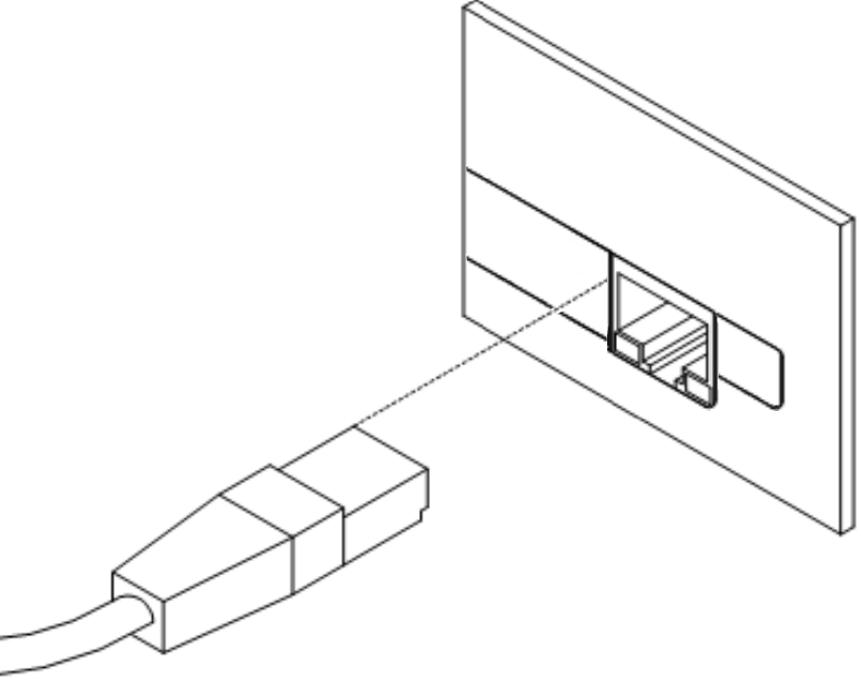
Ethernet Interface
The router features one Ethernet interface (ETH), accessible via an RJ45 panel socket. The Ethernet signal ports are isolated from the ground with a barrier of 1500 V. The pinout is as follows:
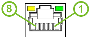
| Pin | Signal Mark | Description |
|---|---|---|
| 1 | TXD+ | Transmit Data — positive pole |
| 2 | TXD- | Transmit Data — negative pole |
| 3 | RXD+ | Receive Data — positive pole |
| 4 | — | — |
| 5 | — | — |
| 6 | RXD- | Receive Data — negative pole |
| 7 | — | — |
| 8 | — | — |
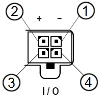
Power Supply and IO
The router is powered through a 4-pin PWR/IO panel socket. The PWR/IO interface also provides digital input and output connectivity.
| Pin Number | Signal Mark | Description |
|---|---|---|
| 1 | GND(-) | Negative pole of DC supply voltage |
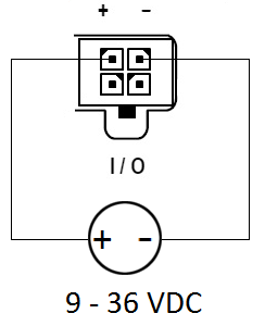
| 2 | VCC(+) | Positive pole of DC supply voltage (+9 to +36 V DC, 1 A) |
| 3 | IN0 | Digital input |
| 4 | OUT0 | Digital output |
Warning
The router must be powered by a supply classified as a Limited Power Source (LPS) according to Annex Q of IEC 62368-1:2014. If the provided power cable is not used, use cables with a minimum wire cross-section of 0.5 mm².
The power supply must provide +9 V to +36 V DC with a current output of at least 1 A. The router includes protection against reversed polarity without signaling.
Warning
Grounding the negative pole disables the reversed polarity protection.
Tips
The router restarts automatically after a power supply outage and subsequent restoration.
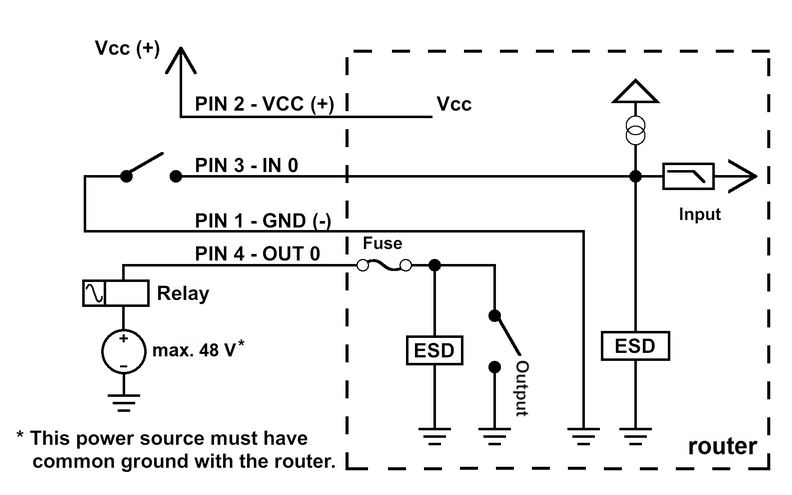
Digital Input
| Logical State | Voltage | Web Interface Status |
|---|---|---|
| Logic 0 | 0 – 0.7 V | On |
| Logic 1 | 1.6 – 36 V | Off |
Check the digital input status in the shell using the io get bin0 command.
Digital Output
The digital output is open in the default configuration. The output current is limited by a resettable fuse (200 mA).
Low Power Mode (LPM)
Warning
In applications requiring low power consumption, such as solar power (not 24/7 operation), use LPM before powering down the entire router.
LPM minimizes power consumption by placing the router in a sleep state. Activate LPM using the lpm command. Wake the router from LPM using the BIN0 input or after a preset duration. Refer to the Command Line Interface application note for detailed instructions.
Grounding
Tips
All metal parts are connected together with the negative pole of the power supply (common pole). Note that the router box may not be directly connected to the negative pole.
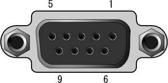
RS232 Interface
The RS232 interface is accessible via a DB9 female connector on the front panel. The pinout is as follows:
| Pin | Signal Mark | Description |
|---|---|---|
| 1 | DCD | Data Carrier Detect |
| 2 | RXD | Receive Data |
| 3 | TXD | Transmit Data |
| 4 | DTR | Data Terminal Ready |
| 5 | GND | System Ground |
| 6 | DSR | Data Set Ready |
| 7 | RTS | Request to Send |
| 8 | CTS | Clear to Send |
| 9 | RI | Ring Indicator |
LED Indicators
The front panel includes three status LEDs. The ETH port has two additional LEDs.
| Caption | Color | State | Description |
|---|---|---|---|
| PWR | Green | On | Router is ready. |
| Green | Blinking | Starting the router. | |
| Green | Fast blinking | Updating firmware. | |
| DAT | Red | Blinking | Communication in progress on the radio channel. |
| WAN | Yellow | Fades out 1× per 5 s | Signal strength is good. |
| ~ | Fades out 1× per 2 s | Signal strength is fair.¹ | |
| ~ | Fades out 1× per 1 s | Signal strength is poor.² | |
| ETH | Green | On | 100 Mbps selected. |
| Green | Off | 10 Mbps selected. | |
| Yellow | On | The network cable is connected. | |
| Yellow | Blinking | Data transmission. | |
| Yellow | Off | The network cable is not connected. |
¹ Or if the difference between neighboring cells is exactly 3 dBm.
² Or if the difference between neighboring cells is less than 3 dBm.
Tips
The WAN LED status is updated every 10 seconds.
Reset Options
The RST button has multiple functions. For details, refer to Initial Configuration → Reset.
Tips
Use a narrow screwdriver or a small tool to press the RST button.