Mounting and Installation
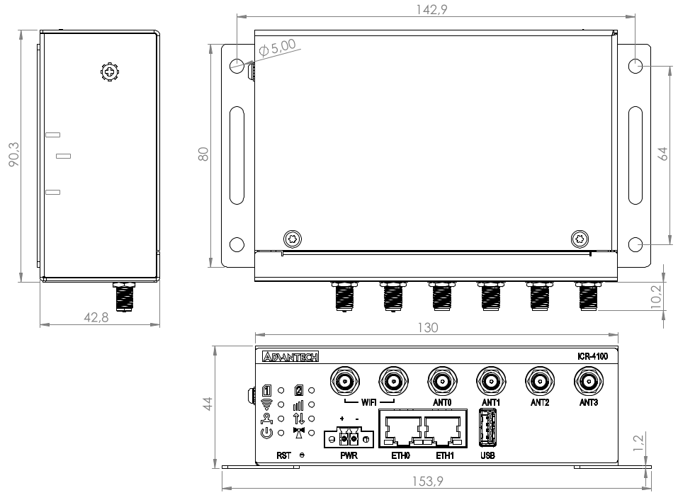
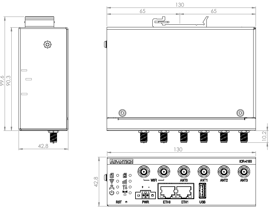
Product Dimensions
Refer to the diagrams below for detailed measurements (in millimeters).
Mounting Options
The router can be installed in the following ways:
- On a Flat Surface: Place the router on a stable, flat surface.
- On a Wall: Use the wall-mounting clips provided with the router. Refer to the Wall Mounting section for detailed instructions.
- On a DIN Rail: Mount the router using the metal DIN rail clip in compliance with EN 60715 standards. Refer to the DIN Rail Mounting section for additional details.
For most applications involving a built-in router within a switchboard, consider the following environmental types:
- Non-public industrial environments: Low voltage with high interference.
- Public environments: Low voltage without high interference.
For both cases, mounting the router to a switchboard eliminates the need for additional immunity or EMC-related examinations under EN 61439-1:2011.
Guidelines for Mounting
In compliance with EN 61439-1:2011, observe the following assembly instructions when mounting the router inside a switchboard:
- When using whip antennas, maintain a minimum distance of 6 cm from cables and metal surfaces on all sides to minimize interference.
- Use a lightning conductor for external antennas mounted outside the switchboard.
- When mounting the router on sheet-steel, use a cable antenna.
- Bundle power supply and data cables, ensuring:
- The combined cable length does not exceed 1.5 m.
- Surge protectors are installed if data cables exceed 1.5 m or run toward the switchboard.
- Data cables are not bundled with mains voltage cables (230 V/50 Hz or 120 V/60 Hz).
- Leave sufficient space between connectors for easy cable handling.
- Use an earth-bonding distribution frame to properly ground the router's grounding screw.
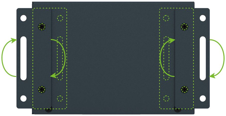
Wall Mounting
Tips
The wall-mounting clips are included as a standard accessory with the router.
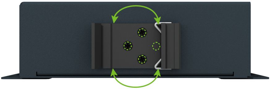
The router can be mounted on a wall or similar surface using the two pre-assembled wall-mounting clips. Rotate the clips as shown in the diagram below before installation.
Each clip has two holes with a diameter of 5 mm for screw placement. Refer to the Product Dimensions section for precise spacing.
Warning
Tighten the wall-mounting clip screws to a maximum torque of 0.4 Nm.
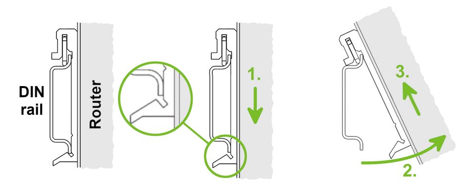
DIN Rail Mounting
The DIN rail clip allows the router to be mounted on a DIN rail compliant with EN 60715 standards. The default clip position is shown below. If necessary, the clip can also be rotated vertically.
Warning
Tighten the DIN rail clip screws to a maximum torque of 0.4 Nm.
To remove the router:
- Push down lightly on the router until the bottom part of the DIN rail clip disengages from the rail.
- Tilt the bottom part of the router away from the rail to release it.