Introduction
The v4i (ICR-4100/4200) product family consists of industrial LTE and 5G routers designed to address diverse industrial requirements. The ICR-4100 series provides the essential interface set, while the ICR-4200 series adds two switchable RS232/RS485 serial interfaces and digital I/O. For additional details, see Functionalities and Scenarios.
The secure, password-protected web interface enables users to monitor detailed statistics, including activity logs, signal strength, and system logs. For guidance on first-time setup, refer to Initial Configuration.
Model Overview
The v4i product family includes several models, each tailored to specific regions and applications. The table below summarizes the available models and their features.
Tips
Order code suffix W = dual-band Wi-Fi 6/6E module. The ICR-4100 series has no serial or I/O interfaces; the ICR-4200 series provides four digital inputs, two digital outputs, and two serial interfaces, each independently switchable to RS232 or RS485.
| Order Code | Region | Cellular | ETH | I/O | Serial | USB | SD | SIM | WiFi | GNSS |
|---|---|---|---|---|---|---|---|---|---|---|
| ICR-4133 | EMEA | LTE Cat.6 | 2 | – | – | ✓ | ✓ | ✓ | – | ✓ |
| ICR-4133W | EMEA | LTE Cat.6 | 2 | – | – | ✓ | ✓ | ✓ | ✓ | ✓ |
| ICR-4233 | EMEA | LTE Cat.6 | 2 | ✓ | ✓ | ✓ | ✓ | ✓ | – | ✓ |
| ICR-4233W | EMEA | LTE Cat.6 | 2 | ✓ | ✓ | ✓ | ✓ | ✓ | ✓ | ✓ |
| ICR-4161 | EMEA | 5G NR | 2 | – | – | ✓ | ✓ | ✓ | – | ✓ |
| ICR-4161W | EMEA | 5G NR | 2 | – | – | ✓ | ✓ | ✓ | ✓ | ✓ |
| ICR-4261 | EMEA | 5G NR | 2 | ✓ | ✓ | ✓ | ✓ | ✓ | – | ✓ |
| ICR-4261W | EMEA | 5G NR | 2 | ✓ | ✓ | ✓ | ✓ | ✓ | ✓ | ✓ |
| ICR-4172 | EMEA-NAM | 5G NR | 2 | – | – | ✓ | ✓ | ✓ | – | ✓ |
| ICR-4172W | EMEA-NAM | 5G NR | 2 | – | – | ✓ | ✓ | ✓ | ✓ | ✓ |
| ICR-4272 | EMEA-NAM | 5G NR | 2 | ✓ | ✓ | ✓ | ✓ | ✓ | – | ✓ |
| ICR-4272W | EMEA-NAM | 5G NR | 2 | ✓ | ✓ | ✓ | ✓ | ✓ | ✓ | ✓ |
✓ = included · – = not available · hover a heading or cell for details
Hardware Components
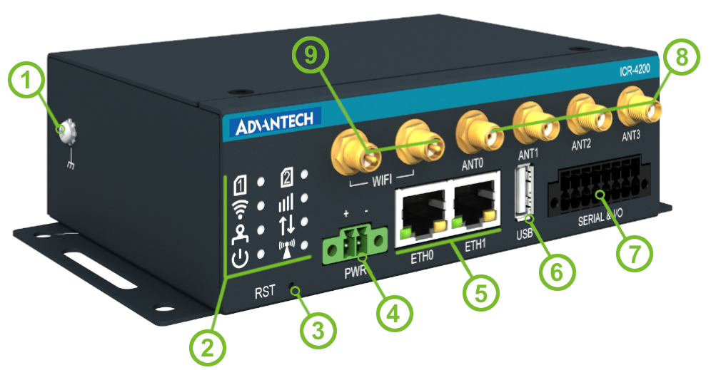
The v4i series supports a wide array of hardware features, as illustrated in the image below. Refer to the Model Overview section for model-specific details.
| # | Caption | Type | Description |
|---|---|---|---|
| 1 | GND Screw | M3 | Ensure proper grounding; see Power Supply. |
| 2 | LEDs | — | Status LED indicators; see LED Indicators. |
| 3 | RST | — | Button to reboot the router or restore the defaults; see Reset. |
| 4 | PWR | 2-pin terminal | Power supply socket; see Power Supply. |
| 5 | ETH0, ETH1 | RJ45 | 1 Gb Ethernet LAN interfaces; see Ethernet Interfaces. |
| 6 | USB | USB-A | USB 3.0 host port; see USB Port. |
| 7 | Serial & I/O | 16-pin terminal | Two switchable RS232/RS485 interfaces, four digital inputs, and two digital outputs, ICR-4200 series only; see Serial and I/O Port and I/O Parameters. |
| 8 | Antenna Connectors | SMA female | Cellular module and GNSS antenna connectors — the exact layout depends on the model (see the note below); see Antenna Connections, Cellular Module Parameters, and GNSS Parameters. |
| 9 | WIFI | RP-SMA female | Connectors for the Wi-Fi antennas (W models); the right-hand Wi-Fi connector can be used for a Bluetooth antenna; see Antenna Connections, Wi-Fi Parameters, and Bluetooth Parameters. |
| # | Caption | Type | Description |
|---|---|---|---|
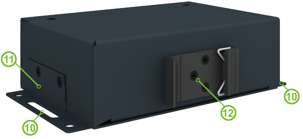
| 10 | Wall Clips | — | Wall mounting clips, included as standard accessories; see Wall Mounting. |
| 11 | SIM Slots, microSD Slot, Serial Switch | Mini SIM, microSD, DIP switch | Two Mini SIM card slots and a microSD card slot; on the ICR-4200 series, the DIP switch beneath the metal SIM cover independently switches each serial interface to RS232 or RS485. See SIM Card Slots, MicroSD Card, and Serial and I/O Port. |
| 12 | DIN Clip | — | DIN mounting clip, included as a standard accessory; see DIN Rail Mounting. |
Antenna layout differences
- ICR-4133, ICR-4233: dedicated GNSS connector plus ANT (main) and DIV (diversity) connectors.
- ICR-4161, ICR-4261: four connectors ANT0–ANT3; ANT1 and ANT3 are shared with GNSS.
- ICR-4172, ICR-4272: dedicated GNSS connector plus four connectors ANT0–ANT3.
Package Contents
Each router package includes the following:
| Item | Description | Image | Quantity |
|---|---|---|---|
| Router | v4i series router; the wall clips and the DIN rail clip come mounted on the router |  | 1 |
| Power Terminal Block | 2-pin terminal block for the power supply; pre-installed on the router | 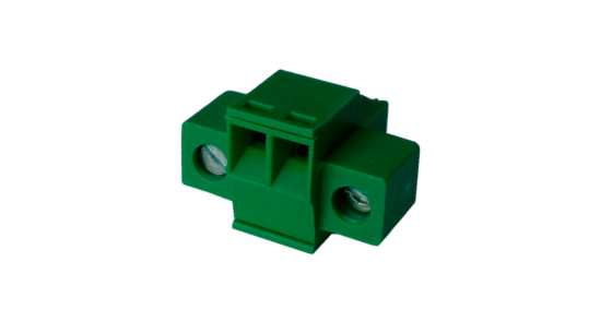 | 1 |
| Serial & I/O Terminal Block | 16-pin terminal block; ICR-4200 series only, pre-installed on the router |  | 1 |
| Quick Start Guide | Printed quick start guide included in the package |  | 1 |
Product Revisions
The revision history below summarizes key updates to the v4i product line. Note that some revisions may not be available for certain order codes. The revision number is printed on the packaging and product labels and is visible in the web interface: Status → General → System Information → Product Revision (the default revision 1.0 may not be shown there).
| Rev.# | Description |
|---|---|
| 1.0 | Initial version (revision not printed on the labels). |
| 1.1 | On the chassis: 7 SMA holes instead of 6 (PCN-2024-05). |