Live Data Updates
Tips
All status pages can display live data. To enable this feature, click on the refresh button in the top right corner on the status page. To stop the data update and to limit the amount of data transferred, disable automatic data updates by clicking the pause button again.
General
You can reach a summary of basic router information and its activities by opening the General status page. This page is displayed when you log in to the device by default. The information displayed on this page is divided into several sections, based upon the type of the router and its hardware configuration. Typically, there are sections for the mobile connection, LAN, system information, and eventually for the WiFi and peripheral ports, if the device is equipped with them.
Tips
IPv6 Address item can show multiple different addresses for one network interface. This is standard behavior since an IPv6 interface uses more addresses. The second IPv6 Address showed after pressing More Information is an automatically generated EUI-64 format link local IPv6 address derived from the MAC address of the interface. It is generated and assigned the first time the interface is used (e.g., cable is connected, Mobile WAN connecting, etc.).
Sections
- Mobile Connection: Displays details about the active SIM card and network connection.
- LAN: Provides information about the local network configuration.
- System Information: Summarizes hardware and software details of the router.
- WiFi (if equipped): Shows details about WiFi configuration and status.
- Peripheral Ports (if equipped): Lists connected peripheral devices.
Mobile Connection Parameters
Item | Description |
|---|---|
| SIM Card | Identification of the SIM card |
| Interface | Defines the interface |
| Flags | Displays network interface flags: None - no flags, Up - administratively enabled, Running - operational state (cable detected), Multicast - multicast capable |
| IP Address | IP address of the interface |
| MTU | Maximum packet size that the equipment can transmit |
| Rx Data | Total number of received bytes |
| Rx Packets | Received packets |
| Rx Errors | Erroneous received packets |
| Rx Dropped | Dropped received packets |
| Rx Overruns | Lost received packets because of overload |
| Tx Data | Total number of sent bytes |
| Tx Packets | Sent packets |
| Tx Errors | Erroneous sent packets |
| Tx Dropped | Dropped sent packets |
| Tx Overruns | Lost sent packets because of overload |
| Uptime | Indicates how long the connection to the cellular network has been established |
This table provides detailed insights into the mobile connection parameters. For additional information, refer to related sections in the documentation.
Ethernet
Each Ethernet interface has a dedicated section on the General status page. The items displayed here have the same meaning as those in the Mobile Connection section. Additionally, the MAC Address item shows the MAC address of the corresponding router interface. The visible information depends on the Ethernet configuration; see Ethernet for details.
WiFi
If the router is equipped with a WiFi module, the WiFi AP section will display information about the WiFi interface operating in access point mode. For configuration details, see WiFi AP.
The WiFi STA section displays information about the WiFi interface operating in station mode. For configuration details, see WiFi STA.
The items displayed in this section have the same meaning as those in the Mobile Connection section.
Peripheral Ports
These items are reported only for devices equipped with serial or binary interfaces.
Info
Available only for ICR-42xx models.
| Item | Description |
|---|---|
| Expansion Port 1 | An interface detected on the first expansion port. |
| Expansion Port 2 | An interface detected on the second expansion port. |
| Digital Input 0 | State of digital input 0. |
| Digital Input 1 | State of digital input 1. |
| Digital Input 2 | State of digital input 2. |
| Digital Input 3 | State of digital input 3. |
| Digital Output 0 | State of digital output 0. |
| Digital Output 1 | State of digital output 1. |
Info
For the voltage levels of the binary I/O ports, refer to the Hardware Manual for your specific router model.
Geolocation
Info
This information is available only on router models equipped with a GNSS module and only when the GNSS service is enabled.
This section displays the router's current position, as determined by the GNSS receiver.
| Item | Description |
|---|---|
| Latitude | The router's current north-south position, expressed in degrees. |
| Longitude | The router's current east-west position, expressed in degrees. |
| Altitude | The router's current height above sea level, measured in meters. |
| Speed over ground | The router's current speed, measured in kilometers per hour. |
| Course over ground | The direction in which the router is moving, expressed in degrees relative to true north. |
| Show on map | Clicking this link opens the router's current position in Google Maps in your default web browser. |
Geolocation information
GNSS
Info
This information is available only on router models equipped with a GNSS module and only when the GNSS service is enabled.
This section displays detailed information about the satellite signals and the receiver's status.
| Item | Description |
|---|---|
| Current Time (UTC) | The current time obtained from the satellite signals, expressed in Coordinated Universal Time (UTC). |
| Fix Type | The type of position fix. A 2D fix requires at least three satellites and provides latitude and longitude. A 3D fix requires at least four satellites and provides latitude, longitude, and altitude. |
| HDOP | Horizontal Dilution of Precision. A measure of the geometric quality of the satellite configuration. A lower value indicates higher positional accuracy. |
| Satellites Used | The number of satellites currently being used for the position fix out of the total number of visible satellites. |
| Satellites | The list of Pseudo-Random Noise (PRN) numbers for all visible satellites. |
| SNR | Signal-to-Noise Ratio for each visible satellite. A higher value indicates a stronger and clearer signal. A hyphen (-) indicates that the satellite is visible but its signal is too weak to be measured. |
| Used | Indicates whether a specific satellite is being used in the position calculation (Y for Yes, N for No). |
GNSS information
Security information
This section provides information about the logged-in user, their last login time, IP address, and the number of failed login attempts.
Security Information
This section provides information about the currently logged-in user, including their last login time, the IP address from which they connected, and the number of failed login attempts since the last successful login.
System Information
System information about the device is displayed in the System Information section.
| Item | Description |
|---|---|
| Product Name | Name of the product (may not match the P/N or order code). |
| Product Type | Type of the product (may be N/A or the same as the Product Name). |
| Firmware Version | Information about the firmware version. |
| Serial Number | Serial number of the router (N/A if not available). |
| Hardware UUID¹ | Unique hardware identifier for the device. |
| Product Revision¹ | Manufactured product revision number. |
| Profile | Current profile — standard or alternative profiles (profiles are used, for example, to switch between different modes of operation). |
| Free Space | Available free space for Router Apps and user data. |
| CPU Usage | CPU usage value (enable refresh in the top-right corner). |
| Memory Usage | Memory usage value (enable refresh in the top-right corner). |
| Supply Voltage¹ | Router supply voltage. |
| Temperature¹ | Internal router temperature. |
| Time | Current date and time. |
| Uptime | Duration the router has been running. |
| Licenses | Link to the list of open-source software components in the firmware along with their license types. Click on a license type to view its text. |
¹ Some models may not support this item.
Mobile WAN
The Mobile WAN menu item provides real-time information about the router's mobile network connection for cellular models. The first section of this page, Mobile Network Information, displays key details about the mobile network in which the router operates. It also includes information about the installed cellular module.
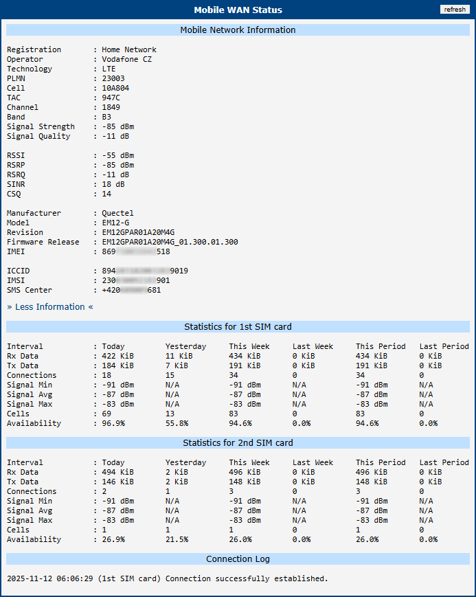
Mobile Network Information
| Item | Description |
|---|---|
| Registration | Current network registration status. |
| Operator | Name of the operator whose network the router is connected to. |
| Technology | Transmission technology used for the connection. |
| PLMN | Public Land Mobile Network (PLMN) code of the operator. |
| Cell | Identifier of the cell the router is connected to (hexadecimal format). |
| LAC/TAC | Unique number (hexadecimal format) assigned to each location area: • LAC (Location Area Code) for 2G/3G networks. • TAC (Tracking Area Code) for 4G/5G networks. |
| Channel | Channel on which the router communicates: • ARFCN for GPRS/EDGE networks. • UARFCN for UMTS/HSPA networks. • EARFCN for LTE networks. • NR-ARFCN for 5G NR networks. |
| Band | Cellular band abbreviation. |
| Signal Strength | Signal strength (in dBm) of the selected cell. |
| Signal Quality | Signal quality of the selected cell. |
| RSSI, RSRP, RSRQ, SINR | Additional signal metrics providing deeper insight into connection quality. Availability depends on the cellular module and technology. |
| CSQ | Cell signal strength value ranges: • 2 – 9 = Marginal • 10 – 14 = OK • 15 – 19 = Good • 20 – 30 = Excellent |
| Neighbours | Signal strength of neighboring hearing cells (GPRS only)¹. |
| Manufacturer | Manufacturer of the installed cellular module. |
| Model | Model of the installed cellular module. |
| Revision | Firmware revision of the cellular module. |
| Firmware Release | Full firmware version string of the cellular module, used for managing Firmware Over-The-Air (FOTA) updates. |
| IMEI / MEID | International Mobile Equipment Identity (IMEI) or Mobile Equipment Identifier (MEID) — the unique hardware identifier of the cellular module. |
| ICCID | Integrated Circuit Card Identifier (ICCID), a globally unique serial number of the SIM card. |
| IMSI | International Mobile Subscriber Identity (IMSI) — a unique number that identifies the SIM card on the mobile network. |
| SMS Center | Phone number of the Short Message Service Center (SMSC) provided by the mobile operator. |
¹ If a neighboring cell in GPRS mode is highlighted in red, the router may frequently switch between the neighboring and primary cell, affecting performance. To prevent this, reorient the antenna or use a directional antenna.
The signal strength value is color-coded: black for good, orange for fair, and red for poor. The following table provides reference ranges for each technology.
| Signal Level | 2G/3G (RSSI/RSCP) | 4G (RSRP) | 5G (RSRP) |
|---|---|---|---|
| Good | > -75 dBm | > -90 dBm | > -90 dBm |
| Fair | -75 dBm to -94 dBm | -90 dBm to -109 dBm | -90 dBm to -119 dBm |
| Poor | < -94 dBm | < -109 dBm | < -119 dBm |
Periods
| Period | Description |
|---|---|
| Today | Today from 0:00 to 23:59 |
| Yesterday | Yesterday from 0:00 to 23:59 |
| This week | This week from Monday 0:00 to Sunday 23:59 |
| Last week | Last week from Monday 0:00 to Sunday 23:59 |
| This period | This accounting period |
| Last period | Last accounting period |
Connection Statistics
This section provides usage and performance data for each SIM card over various time periods. The accounting periods can be customized on the Configuration → Mobile WAN page.
| Item | Description |
|---|---|
| RX data | Total volume of received data. |
| TX data | Total volume of sent data. |
| Connections | Total number of successful network connections established. |
| Signal Min | Minimum signal strength recorded during the period. |
| Signal Avg | Average signal strength during the period. |
| Signal Max | Maximum signal strength recorded during the period. |
| Cells | Number of times the router switched between cell towers. |
| Availability | Percentage of time the router was successfully connected to the network. Calculated from the activation of the relevant SIM card; only active SIM cards are included. |
Tips
Hovering over the minimum or maximum signal strength value reveals the timestamp of its last occurrence.
Connection Log
This section displays a detailed, real-time log of events related to the mobile network connection. It is an invaluable tool for troubleshooting, as it records the step-by-step process of network registration and clearly indicates any errors encountered.
WiFi
Status
The Status → Wi-Fi page displays the current operational status of the Wi-Fi module and all configured interfaces, including Access Point (AP) and Station (STA) modes.
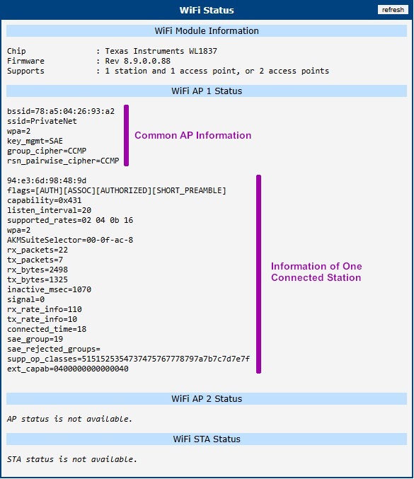
Wi-Fi Module Information
This section provides hardware-specific details about the installed Wi-Fi module.
| Item | Description |
|---|---|
| Chip | The model of the Wi-Fi chipset. |
| Firmware | The version of the firmware running on the Wi-Fi module. |
| Supports | Lists the number of simultaneous interfaces the module can handle. For example, 1 station and 2 access points indicates that the router can act as a client to one network while concurrently operating two separate access point interfaces. |
Wi-Fi AP Status
The WiFi AP 1 Status and WiFi AP 2 Status sections display information about the Wi-Fi interfaces operating in Access Point mode. This includes common AP settings followed by a list of connected stations (clients). Each block of connected station data begins with the client's MAC address, followed by the items described in the tables below.
Common AP Information
| Column/Item | Description |
|---|---|
| bssid | The MAC address of the Wi-Fi access point interface. |
| ssid | The Service Set Identifier (network name) broadcast by the access point. |
| wpa | Indicates the WPA standard version bitmask currently in use (e.g., 2 indicates support for WPA2/RSN standards). Note that WPA3 also utilizes the RSN framework; to distinguish between WPA2 and WPA3, refer to the key_mgmt field. |
| key_mgmt | The Key Management Method used for authentication. Common values include WPA2-PSK (WPA2 Personal) and SAE (WPA3 Personal). |
| group_cipher | The encryption protocol used for broadcast and multicast traffic within the network (e.g., CCMP, TKIP). |
| rsn_pairwise_cipher | Encryption protocol used for unicast traffic (e.g., CCMP). |
Connected Station Information
| Column/Item | Description |
|---|---|
| [MAC Address] | The MAC address of the connected client device. |
| flags | Connection flags indicating current state (e.g., [AUTH], [ASSOC], [AUTHORIZED]). |
| capability | A hexadecimal bitmask indicating the station's advertised capabilities (e.g., support for ESS, IBSS, Privacy, Short Preamble) as defined in the IEEE 802.11 standard. |
| listen_interval | The number of beacon intervals for which the station may enter power-saving mode (sleep) before waking up to receive beacon frames. |
| supported_rates | A list of data transmission rates (in Mbps or hexadecimal representation) that the station supports. |
| wpa | Indicates the WPA standard version currently in use for this connection (e.g., 2 indicates support for WPA2/RSN standards). Note that WPA3 also utilizes the RSN framework. |
| AKMSuiteSelector | The Authentication and Key Management suite selector used. It identifies the authentication method (e.g., 00-0f-ac-8 for SAE/WPA3 or 00-0f-ac-2 for WPA2-PSK). |
| rx_packets | Number of packets received from this station. |
| tx_packets | Number of packets transmitted to this station. |
| rx_bytes | Number of bytes received from this station. |
| tx_bytes | Number of bytes transmitted to this station. |
| inactive_msec | The time in milliseconds since the last data packet was received from the station. A lower value indicates an active connection. |
| signal | Signal strength of the connected station (in dBm). |
| rx_rate_info | Information about the last received data rate from the station (e.g., bitrate index or MCS index). |
| tx_rate_info | Information about the last transmitted data rate to the station (e.g., bitrate index or MCS index). |
| connected_time | Duration of the current connection in seconds. |
| sae_group | The Diffie-Hellman group (ECC curve) used during the WPA3 SAE handshake (e.g., 19 for NIST P-256). Only applicable when WPA3 (SAE) is used. |
| sae_rejected_groups | A list of SAE groups that were proposed but rejected during the handshake process. |
| supp_op_classes | Supported Operating Classes. A hexadecimal string listing the frequency bands and channel behaviors the station supports. |
| ext_capab | Extended Capabilities. A hexadecimal bitfield indicating support for advanced features (e.g., BSS Transition, WNM) beyond the standard capability field. |
Wi-Fi STA Status
The WiFi STA Status section displays information about the Wi-Fi interface operating in Station (Client) mode.
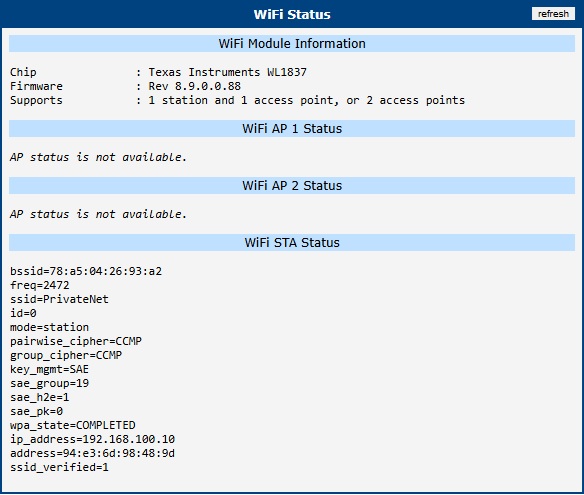
| Item | Description |
|---|---|
| bssid | The MAC address of the Access Point to which the station is connected. |
| freq | The operating frequency (channel) in MHz (e.g., 2472 corresponds to channel 13). |
| ssid | The name of the Wi-Fi network the station is connected to. |
| id | The internal numeric identifier of the configured network profile in the wpa_supplicant. |
| mode | Operation mode (station). |
| pairwise_cipher | The encryption protocol used for unicast data traffic between the station and the access point (e.g., CCMP, GCMP, TKIP). |
| group_cipher | The encryption protocol used for broadcast and multicast traffic within the network (e.g., CCMP, TKIP). |
| key_mgmt | The Key Management protocol used for authentication. Common values include WPA-PSK (WPA2 Personal) and SAE (WPA3 Personal). |
| sae_group | The Diffie-Hellman group (ECC curve) used during the WPA3 SAE handshake (e.g., 19 for NIST P-256). Only applicable when WPA3 (SAE) is used. |
| sae_h2e | Indicates if the "Hash-to-Element" method was used for SAE password derivation. 1 means H2E was used (mandatory for WPA3 in 6 GHz), 0 means the older "Hunting-and-Pecking" loop method was used. |
| sae_pk | Indicates if SAE Public Key (SAE-PK) authentication was used. 1 means SAE-PK was used to cryptographically bind the SSID to the password (preventing rogue APs), 0 means standard SAE was used. |
| wpa_state | The current state of the connection. COMPLETED indicates a successful connection. States like SCANNING or DISCONNECTED imply the router is searching for a network or cannot connect (check credentials or signal). |
| ip_address | The IP address assigned to the station interface, either obtained dynamically from a DHCP server or configured statically. |
| address | The MAC address of the router's Wi-Fi station interface. |
| ssid_verified | Indicates if the SSID has been verified (e.g., 1 for true). Only applicable when WPA3 (SAE) is used. |
Scan
The Status → Wi-Fi → Scan page allows you to discover all nearby Wi-Fi networks. The results are displayed in a list, showing the key parameters of each detected network.
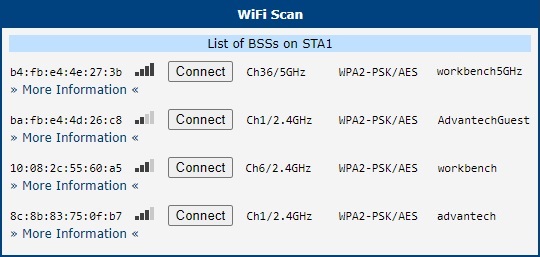
The list is structured into several columns, and each entry provides a Connect button and a link to view More Information.
| Column/Item | Description |
|---|---|
| BSS | The MAC address of the detected access point. |
| Signal Icon | A visual representation of the signal strength. More bars indicate a stronger signal. |
| Connect button | Clicking this button redirects you to the Configuration → Wi-Fi → Station page with the selected network's details pre-filled, allowing you to easily connect by entering the password. |
| Channel/Band | The channel number and frequency band the network is operating on. |
| Security | The security protocol and encryption method used by the network (e.g., WPA2-PSK/AES). |
| SSID | The public name of the Wi-Fi network. |
| More Information | Clicking this link expands a section with detailed technical parameters of the access point, intended for advanced diagnostics. |
Network
To view detailed information about network interfaces, routing tables, and active connections, navigate to the Status → Network page. The upper part of the page displays details for all active network interfaces, followed by the IPv4 and IPv6 routing tables.
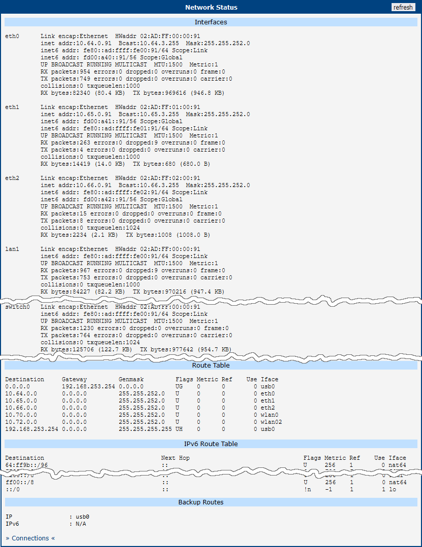
Interfaces
This section provides an overview of all active network interfaces on the router. For each interface, it displays essential information such as assigned IP addresses, MAC address, and traffic statistics. In the table below, the x in an interface name represents its zero-indexed instance number. The availability of specific interfaces depends on the router model and its configuration.
| Interface | Description |
|---|---|
| ethx | A physical Ethernet interface directly connected to the CPU. The index x identifies the interface instance (e.g., eth0, eth1). |
| vlanx | A logical VLAN interface. The index x is an internal interface number and does not match the configured VLAN ID. The actual VLAN ID is defined separately and mapped to this logical interface. |
| lo | The virtual loopback interface used for internal communication within the router. |
| null0 | A virtual interface used by the NAT64 translator. Traffic routed to this interface is discarded. |
| usb0, usb1 | Interfaces representing the cellular WAN connections for the first or second modem module. These interfaces are connected internally via the USB bus. |
| wlanx | A Wi-Fi interface, where x identifies the physical radio or a virtual access point instance. |
| pppoex | A virtual interface for a PPPoE session, where x is the instance number. |
| tunx | A virtual interface for an OpenVPN tunnel, where x is the tunnel instance number (0–3). |
| ipsecx | A virtual interface for an IPsec tunnel, where x is the tunnel instance number (0–3). |
| wgx | A virtual interface for a WireGuard tunnel, where x is the tunnel instance number (0–3). |
| grex | A virtual interface for a GRE tunnel, where x is the tunnel instance number (0–3). |
| l2tp0 | A virtual interface for an L2TP tunnel. Only one instance is supported. |
| pptp0 | A virtual interface for a PPTP tunnel. Only one instance is supported. |
Each active interface provides a detailed summary of its status and traffic statistics. The parameters are described below.
| Item | Description |
|---|---|
| HWaddr | The hardware Media Access Control (MAC) address of the interface. |
| inet addr | The primary IPv4 address assigned to the interface. |
| inet6 addr | The primary IPv6 address assigned to the interface. An interface may have multiple IPv6 addresses. |
| P-t-P | For a point-to-point link, this is the IP address of the remote peer. |
| Bcast | The broadcast address for the interface's subnet. |
| Mask | The subnet mask associated with the IPv4 address. |
| MTU | The Maximum Transmission Unit, indicating the largest packet size (in bytes) that the interface can transmit without fragmentation. |
| Metric | A value used by the routing table to determine the cost of a route. Lower values are preferred. |
| RX/TX packets | The total count of packets received (RX) and transmitted (TX) by the interface. |
| Errors | A count of errors that occurred during reception or transmission. |
| Dropped | The number of packets that were dropped during reception or transmission, often due to a lack of buffer space. |
| Overruns | The number of packets lost due to buffer overloads. |
| Frame | The number of received packets dropped due to framing errors (e.g., incorrect checksums). |
| Carrier | The number of transmission errors related to the physical layer carrier signal. |
| Collisions | The number of packet collisions detected on the physical medium. |
| txqueuelen | The current length of the transmission queue for the interface. |
| RX/TX bytes | The total volume of data in bytes received (RX) and transmitted (TX). |
Routing Tables
The middle of the page shows the kernel routing tables. Both the IPv4 Route Table and the IPv6 Route Table are displayed. Below the main routing tables, the Backup Routes section lists any currently active backup routes.
If NAT64 is enabled (Configuration → NAT → IPv6), it is automatically used for communication between IPv6 and IPv4 networks. This works with the router's DNS64 service, which synthesizes AAAA records from A records. When active, a route for the default NAT64 prefix, 64:ff9b::/96, will be visible in the IPv6 Route Table.
Backup Routes
This section identifies the active primary WAN interface and its corresponding IP address for both IPv4 and IPv6 Internet traffic. The status shown here directly reflects the router's automatic failover system (for details, see Backup Routes), which operates independently of the main routing table. When the primary connection fails, the router automatically switches to a backup interface, and that change is immediately displayed here.
| Parameter | Description |
|---|---|
| WAN IP Interface | Displays the network interface (e.g., eth0, usb0) currently providing the primary outbound path for all IPv4 traffic. If no connection is active, this shows N/A. |
| WAN IP Address | Displays the current IPv4 address assigned to the active WAN interface. |
| WAN IPv6 Interface | Displays the network interface currently providing the primary outbound path for all IPv6 traffic. If no connection is active, this shows N/A. |
| WAN IPv6 Address | Displays the current IPv6 address assigned to the active WAN IPv6 interface. |
LLDP Neighbors
This section displays information about directly connected network devices discovered via the Link Layer Discovery Protocol (LLDP). For this section to be populated, the LLDP service must be enabled in the router's configuration; see LLDP for details.
By default, the page provides a concise summary of all detected neighbors — local interface, the neighbor's MAC address (ChassisID), system name (SysName), and basic port details. To view extended diagnostic data such as hardware descriptions, management IP addresses, device capabilities, and PoE parameters, click the » More Information « link. The following example shows the extended information for an Advantech ICR-3232 router:
Interface:    eth1, via: LLDP, RID: 2, Time: 0 day, 01:03:07
  Chassis:
    ChassisID:    mac 00:11:22:33:44:55
    SysName:      Router
    SysDescr:     ICR-323x 6.6.1 (2026-02-11, commit 2f2ad43db9b08bc71c5d5efe0cf64dfdb0910ff1) #3559
    MgmtIP:       192.168.1.10
    MgmtIP:       fe80::85f:aff:febc:7b1e
    Capability:   Bridge, off
    Capability:   Router, on
    Capability:   Wlan, off
    Capability:   Station, off
  Port:
    PortID:       mac 00:11:22:33:44:55
    PortDescr:    eth0
    TTL:          20
    PMD autoneg:  supported: yes, enabled: yes
      Adv:        10Base-T, HD: yes, FD: yes
      Adv:        100Base-TX, HD: yes, FD: yes
      MAU oper type: 100BaseTXFD - 2 pair category 5 UTP, full duplex mode
Tips
The structure and meaning of LLDP data units (TLVs) are defined by the IEEE 802.1AB standard.
DHCP
Information about the DHCP server activity is accessible via the DHCP item. The DHCP server automatically configures the client devices connected to the router. The DHCP server assigns each device an IP address, subnet mask, and default gateway (IP address of the router) and DNS server (IP address of the router). DHCPv6 server is supported.
See the figure below for the DHCP Status example. Records in the DHCP Status window are divided into two parts based on the interface.
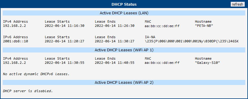
The DHCP Status window displays the following information on a row for each client in the list. All items are described in table below.
| Item | Description |
|---|---|
| IPv4 Address | IPv4 address assigned to a client |
| IPv6 Address | IPv6 address assigned to a client |
| Lease Starts | Time IP address lease began |
| Lease Ends | Time IP address lease expires |
| MAC | Client's MAC address |
| Hostname | Client hostname |
| IA-NA | IPv6 unique identifier |
Info
The DHCP status may occasionally display two records for one IP address, potentially caused by resetting the client network interface.
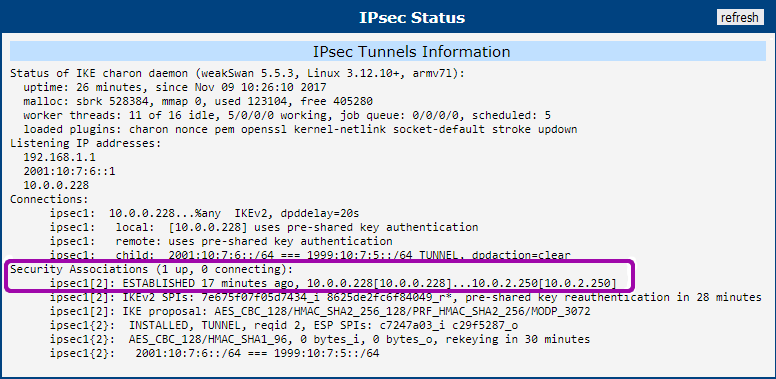
IPsec
To check the status of configured IPsec tunnels, navigate to the Status → IPsec page. This page displays a log of the IPsec connection status.
For a successfully established tunnel, the log will contain the keyword ESTABLISHED. Additionally, the status summary will show the number of active connections, such as 1 up, as highlighted in the figure below.
If the log does not show these indicators (e.g., it shows 0 up), the IPsec tunnel has not been successfully established.
WireGuard
To check the status of configured WireGuard tunnels, navigate to the Status → WireGuard page. This page displays the current operational state and statistics for each active WireGuard interface.
The figure below shows an example of a running WireGuard tunnel.
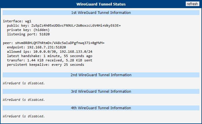
The status page displays the following information for each peer connected to a WireGuard interface.
| Parameter | Description |
|---|---|
| Interface | The name of the WireGuard interface on the router (e.g., wg0). |
| Public key | The public key of the connected peer. |
| Allowed ips | The IP addresses from which this peer is allowed to send traffic through the tunnel. |
| Latest handshake | The time elapsed since the last successful handshake with the peer. A handshake confirms a secure connection. This time is only displayed after data has been exchanged, either from regular traffic or a keepalive packet (if enabled). |
| Transfer | The total amount of data received (rx) and transmitted (tx) through the tunnel for this peer. |
Warning
Latest handshake time will not appear until tunnel communication occurs (data sent by client-side or keepalive data when NAT/Firewall Traversal is set to yes).
DynDNS
The router supports Dynamic DNS using a DNS server. If Dynamic DNS is configured, its status can be viewed by selecting the DynDNS menu option.
Tips
You can use the servers listed below for the Dynamic DNS service. DynDNSv6 can be used when IP Mode is set to IPv6 on the Services → DynDNS configuration page.
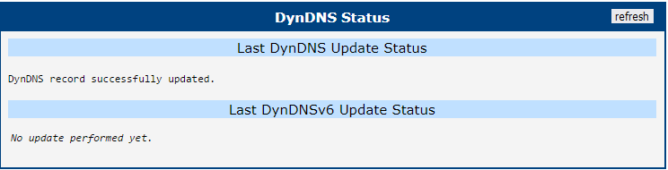
When the router detects a DynDNS record update, the dialog displays one or more of the following messages:
- DynDNS client is disabled.
- Invalid username or password.
- Specified hostname doesn't exist.
- Invalid hostname format.
- Hostname exists, but not under specified username.
- No update performed yet.
- DynDNS record is already up to date.
- DynDNS record successfully update.
- DNS error encountered.
- DynDNS server failure.
Warning
The router's SIM card must have public IP address assigned or DynDNS will not function correctly.
Connections
The Status → Connections page displays a real-time list of all active network connections passing through the router. This overview is particularly useful for monitoring current network traffic and troubleshooting routing or connectivity issues.
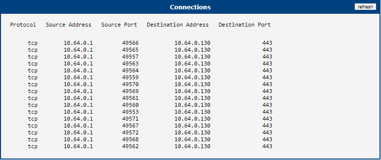
The table below describes the information provided in each column of the connections list.
| Column | Description |
|---|---|
| Protocol | The transport layer protocol used for the connection (e.g., TCP, UDP, or ICMP). |
| Source Address | The originating IP address of the network connection. |
| Source Port | The originating port number of the connection. |
| Destination Address | The target IP address of the network connection. |
| Destination Port | The target port number of the connection. |
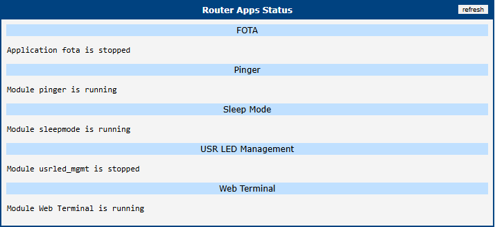
Router Apps
The Status → Router Apps page provides a quick overview of all Router Apps currently installed on the router. This summary allows administrators to easily verify the operational state of each application without needing to navigate to the primary configuration menu of every single Router App.
As shown in the figure below, the page lists each installed Router App and clearly indicates its current status (e.g., whether the application is actively running or currently stopped).
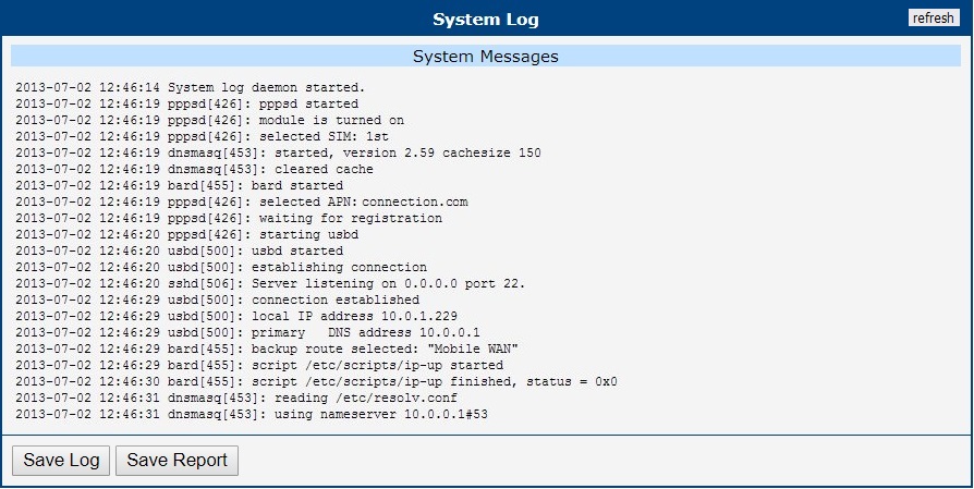
System Log
To view the router's operational logs, navigate to the Status → System Log page. This page displays messages generated by the router's operating system and various services.
Info
For security, sensitive data such as passwords is automatically filtered out from the system log and diagnostic reports.
The level of detail in the log is controlled by the Minimum Severity setting on the Configuration → Services → Syslog page.
The router manages log storage to prevent files from growing indefinitely. By default, the total log size is limited to 10 KiB, split between two rotating files. When the current file is full, the system switches to the other. Once both are full, new entries overwrite the oldest ones. The Log Size Limit can be adjusted on the Syslog configuration page.
The System Log page provides several options for downloading diagnostic information:
Save Log: Downloads the current contents of the system log as a plain text file (
*.log).Save Report: Generates and downloads a comprehensive diagnostic report file (
*.txt), which is essential for troubleshooting and providing to technical support. The report always contains the following information:- General system information and status
- Network statistics and current routing tables
- A list of all running processes
- Filesystem usage information
- The complete system log
Tips
For users logged in with the Admin role, the report additionally includes a copy of the current router configuration. This section is omitted for standard users.
Save Diagnostic Data: Downloads a compressed archive (
*.gz) containing detailed data from the last system failure. This button is only visible to users with the Admin role and is only enabled when a system crash dump is present. The data is intended for advanced analysis by technical support.