Hardware and Connectivity
Refer to the Hardware Components section for a detailed summary of the product's hardware.
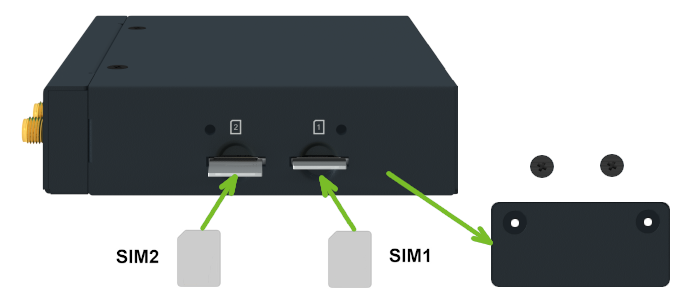
SIM Card Slots
Tips
Models ICR-2031 and ICR-2041 have one SIM card slot. All other models have two SIM card slots.
Slots for two SIM cards are located on the router beneath a metal cover. To communicate over a cellular network, insert an activated, data-provisioned SIM card into a SIM card slot. You can install two SIM cards simultaneously to use the SIM switching feature. You can configure each SIM card with a different APN (Access Point Name).
Tips
SIM card type: Micro SIM (3FF) — 15.0 × 12.0 × 0.76 mm.
Changing the SIM Card
- Always disconnect the router from the power supply before handling the SIM card.
- Unscrew the two screws on the SIM card cover and remove the cover.
- To remove an inserted SIM card, use the flat end of a spudger or your fingernail. Press the card slightly into its slot until you hear a click. Release the card; it will pop out of its slot.
- To insert a SIM card, push the card into the slot until it clicks into place.
- Replace the cover and tighten the two screws.
If the SIM card requires a PIN, enter it in the router's web interface under Administration → Unlock SIM Card.
Antenna Connections
The antenna connectors available depend on the router model:
- ICR-2412, ICR-2413: One SMA female connector — ANT (main) — for the cellular antenna.
- ICR-2431, ICR-2441, ICR-2545, ICR-2452: Two SMA female connectors — ANT (main) and DIV (diversity) — for cellular antennas on the front panel, plus two connectors on the side panel: an RP-SMA female connector (WIFI) for the Wi-Fi antenna and an SMA female connector (GNSS) for the GNSS antenna.
- All other models: Two SMA female connectors — ANT (main) and DIV (diversity) — for cellular antennas on the front panel, and an RP-SMA female connector (WIFI) for the Wi-Fi antenna on the side panel.
Warning
- Always operate the router with a cellular antenna securely connected to the cellular antenna connector. Transmitting without an antenna attached causes RF energy to be reflected at the open connector, which can permanently damage the radio circuitry. Ensure the antenna is properly installed before powering on or transmitting.
- On models ICR-2431 and ICR-2441: if a short circuit occurs on the GNSS input, the cellular module shuts down. It restarts once the short circuit is resolved.
Tips
- The DIV cellular antenna is required for MIMO DL.
- The thread of the WIFI connector is connected to the internal ground.
- The recommended tightening torque for the antenna SMA connectors is 0.9 Nm.
Ethernet Interfaces
Models ICR-2501, ICR-2531, ICR-2631, and ICR-2645 provide three switched ETH0 ports and one ETH1 port. When viewing the router from the front, the first ETH0 port is on the left.
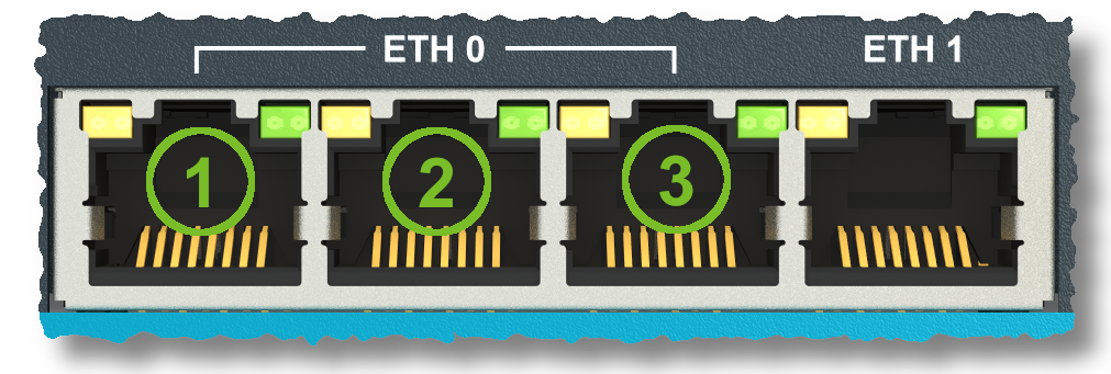
All other models provide one ETH0 port and one ETH1 port. All Ethernet ports are accessible via RJ45 panel sockets.
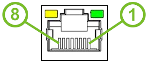
| Pin | Signal | Description |
|---|---|---|
| 1 | Tx+ | Transmit Data+ |
| 2 | Tx− | Transmit Data− |
| 3 | Rx+ | Receive Data+ |
| 4 | — | Not Connected |
| 5 | — | Not Connected |
| 6 | Rx− | Receive Data− |
| 7 | — | Not Connected |
| 8 | — | Not Connected |
Tips
The isolation barrier of the Ethernet ports from ground is 1500 V.
Power Supply
The power supply connects to pins 1 and 2 of the 6-pin terminal block on the left panel. The I/O interface uses pins 3–6 of the same block — see I/O Port.
| Pin | Signal | Description |
|---|---|---|
| 1 | PWR(+) | Positive pole of DC supply voltage (+9 to +48 V DC) |
| 2 | PWR(−) | Negative pole of DC supply voltage |
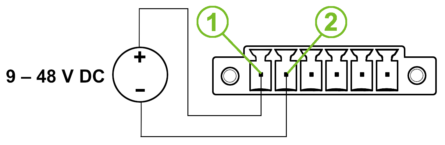
The required supply voltage is +9 to +48 V DC. The router has built-in protection against reversed polarity without signaling.
Warning
Use a power supply specified as a Limited Power Source (LPS) or CEC/NEC Class 2 power supply.
Tips
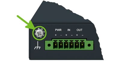
The power supply common pole is not connected to the router's metal chassis or internal ground.
To protect the router, ground it using the grounding screw as shown below.
I/O Port
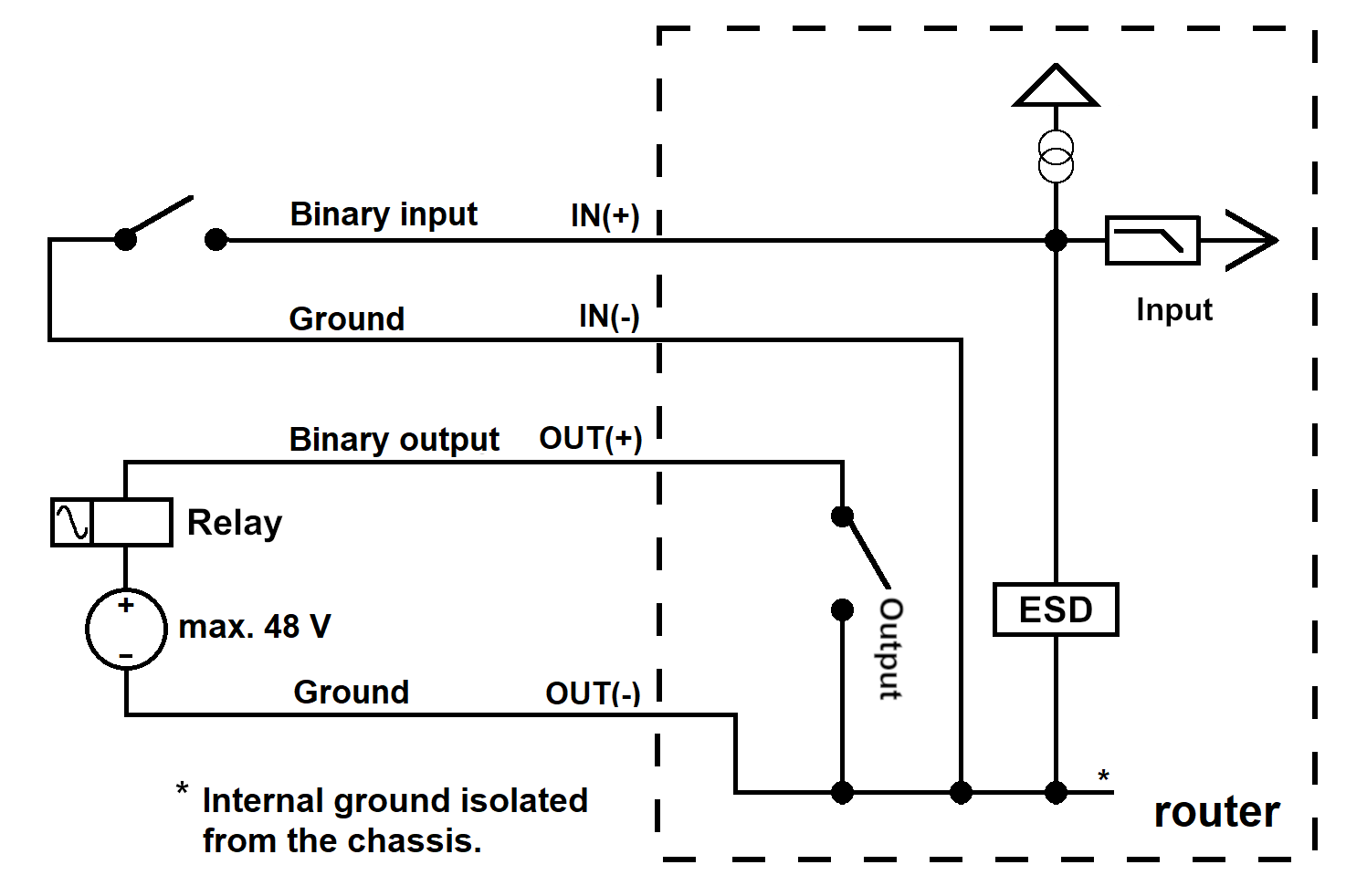
The I/O interface connects to pins 3–6 of the 6-pin terminal block on the left panel. The power supply uses pins 1–2 of the same block — see Power Supply.
Warning
On models ICR-2031, ICR-2041, ICR-2431, and ICR-2441: the maximum length of wires connected to the I/O ports is 3 meters to meet EMC immunity conditions.
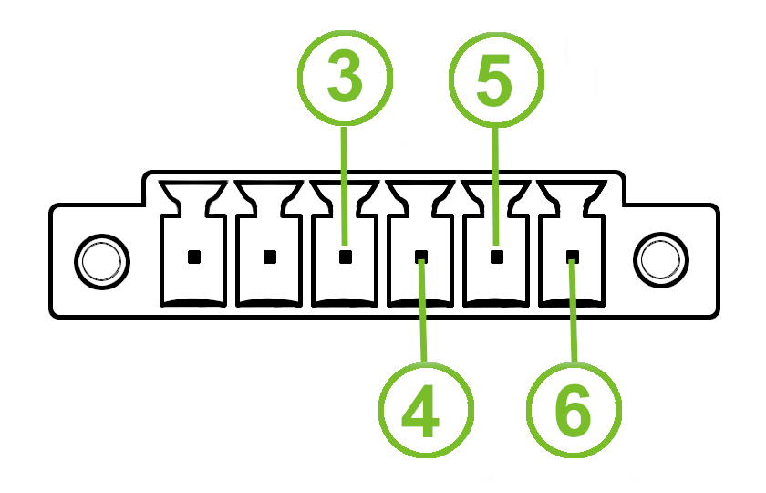
| Pin | Signal | Description |
|---|---|---|
| 3 | IN(+) | Digital input (positive pole) |
| 4 | IN(−) | Digital input (negative pole) |
| 5 | OUT(+) | Digital output (positive pole) |
| 6 | OUT(−) | Digital output (negative pole) |
Serial Interfaces
Tips
The serial interface is not available on all models. Refer to the product specifications to confirm whether your model includes a serial interface.
The RS232 and RS485 serial interfaces connect to a 7-pin terminal block on the left panel.
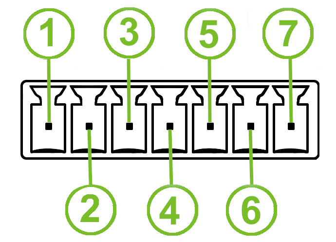
RS485:
| Pin | Signal | Description |
|---|---|---|
| 1 | D (+) | In/Out |
| 2 | D (−) | In/Out |
| 3 | GND | Ground (common with RS232) |
RS232:
| Pin | Signal | Description |
|---|---|---|
| 3 | GND | Ground (common with RS485) |
| 4 | RXD | Received Data |
| 5 | TXD | Transmit Data |
| 6 | RTS | Request to Send |
| 7 | CTS | Clear to Send |
Tips
The serial interfaces are not electrically isolated from the router.
LED Indicators
Status LEDs are located on the front panel of the router. Each ETH connector also has two additional LEDs showing the port status.
| Caption | Color | State | Description |
|---|---|---|---|
| PWR | Green | On | The router is starting up. |
| Green | Blinking | The router is ready (heartbeat). | |
| Green | Fast blinking | The router firmware is being updated. | |
| USR | Green | — | The function of this LED is user-defined. |
| DI | Green | On | The digital input is active. |
| DO | Green | On | The digital output is active. |
| DAT | Green | Blinking | Cellular communication is in progress. |
| SIG | Green | On | Good cellular signal. |
| Green | Blinking | Fair cellular signal. | |
| Green | Fast blinking | Poor cellular signal. | |
| TECH | Green | On | The active SIM uses 4G technology.¹ |
| Green | Blinking | The active SIM uses 3G technology.¹ | |
| Green | Fast blinking | The active SIM uses 2G technology.¹ | |
| SIM | Green | On | SIM1 is active for the cellular connection.² |
| Green | Blinking | SIM2 is active for the cellular connection.² | |
| Green | Fast blinking | A SIM issue (missing card or PIN not entered).² | |
| ETH0, ETH1 | Green | On | Selected 100 Mbps bit rate. |
| Green | Off | Selected 10 Mbps bit rate. | |
| Orange | On | Network cable connected. | |
| Orange | Brief off blinks | Data transmission. | |
| Orange | Off | Network cable not connected. |
Tips
¹ TECH LED states vary by model:
ICR-2413 and ICR-2437 — On = 4G only
ICR-2041, ICR-2438, and ICR-2441 — On = 4G, Blinking = 3G
ICR-2452 — On = 5G, Blinking = 4G; all other models — On = 4G, Blinking = 3G, Fast blinking = 2G.² SIM and ETH LEDs on models ICR-2031 and ICR-2041 (single SIM slot):
SIM LED shows On = SIM active and Fast blinking = SIM issue (no SIM2 state). Only the ETH0 LED is present.
Reset Options
The RST button is located in a small opening on the router panel and has multiple functions. For details, refer to Initial Configuration → Reset.
Tips
Use a narrow screwdriver or a small tool to press the RST button.