Mounting and Installation
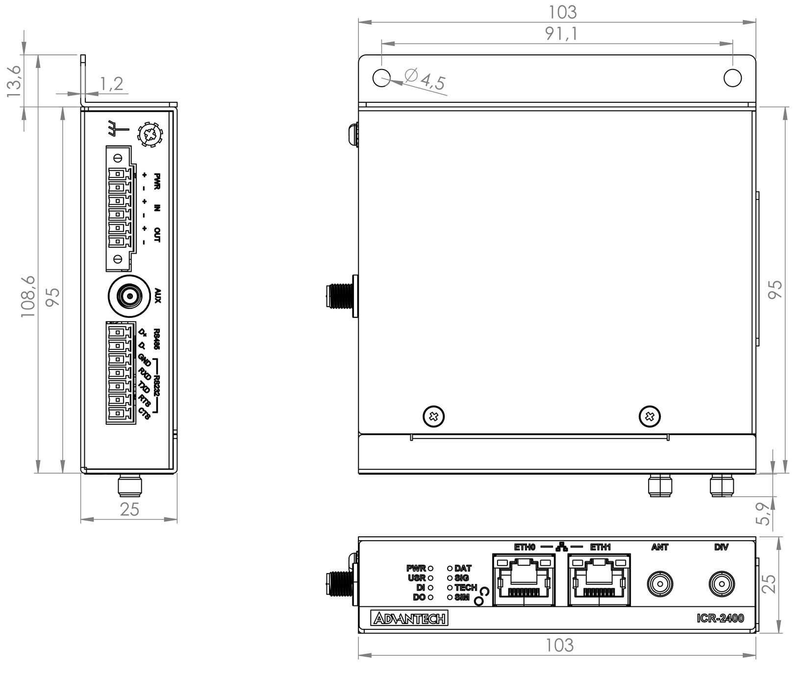
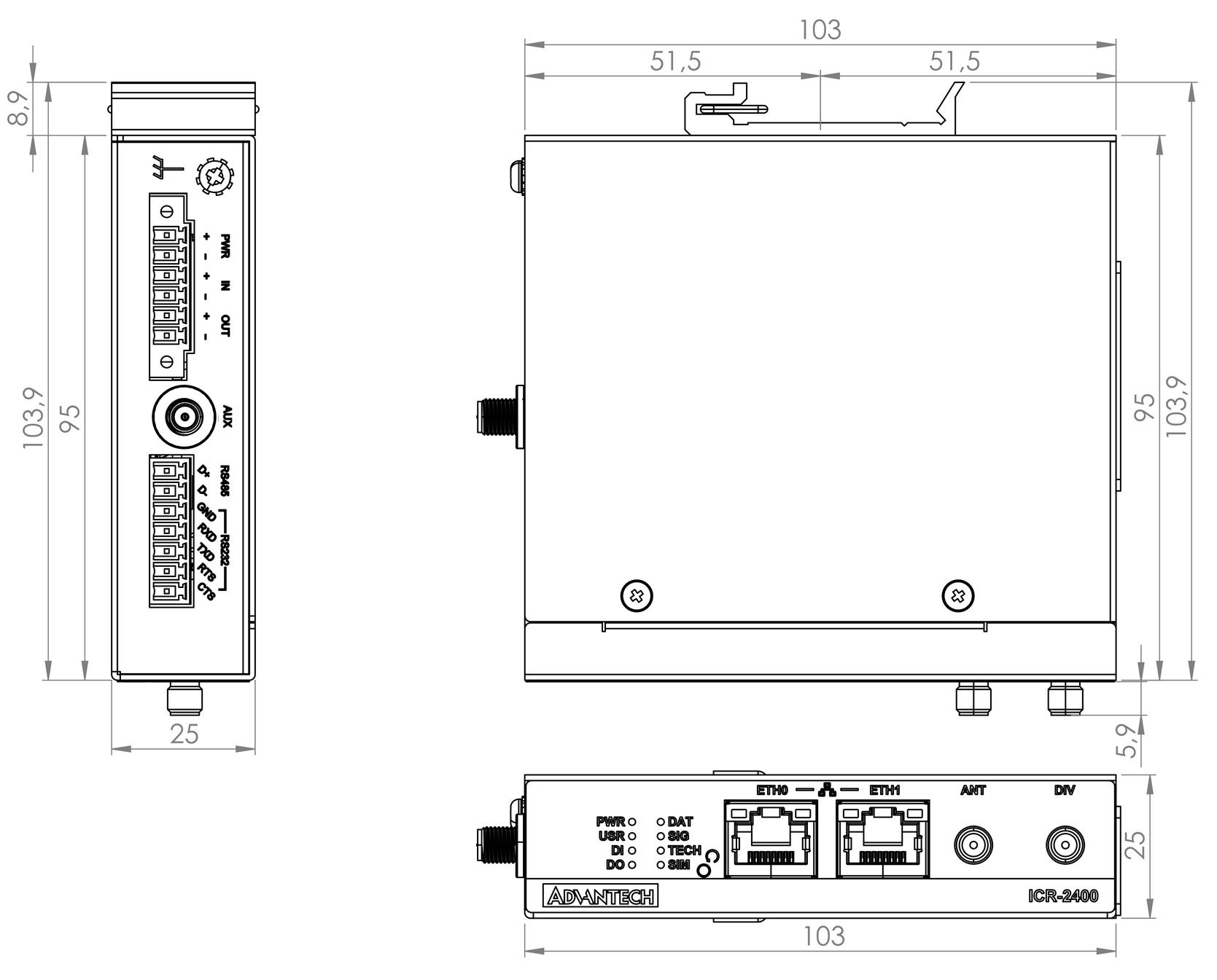
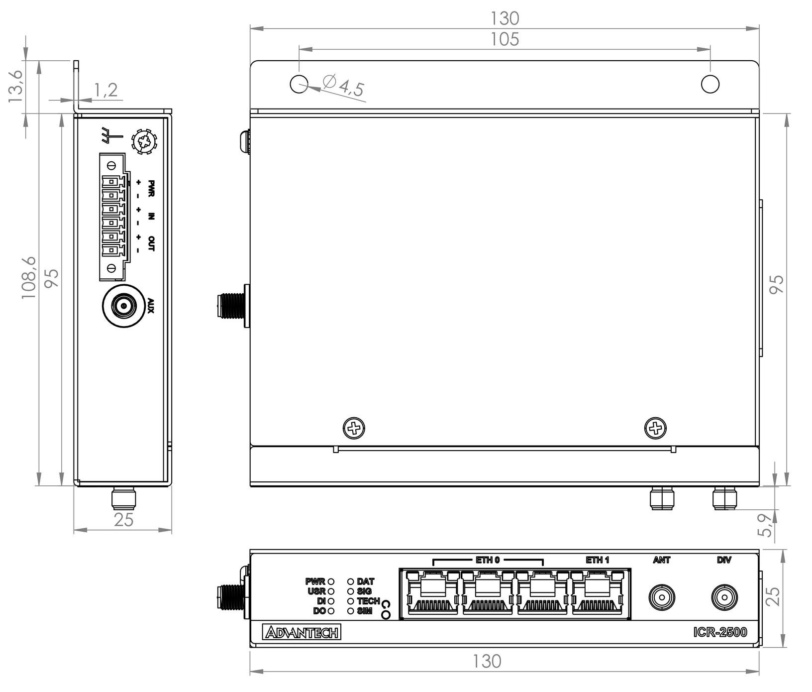
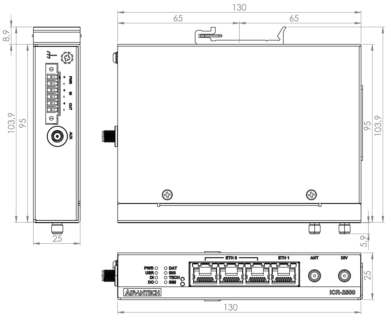
Product Dimensions
Refer to the diagrams below for detailed measurements (in millimeters).
ICR-2000 and ICR-2400 Series
ICR-2500 and ICR-2600 Series
Mounting Options
The router can be installed in the following ways:
- On a Flat Surface: Place the router on a stable, flat surface.
- On a Wall: Use the wall-mounting clip provided with the router. Refer to the Wall Mounting section for detailed instructions.
- On a DIN Rail: Mount the router using the metal DIN rail clip in compliance with EN 60715 standards. Refer to the DIN Rail Mounting section for additional details.
For most applications involving a built-in router within a switchboard, consider the following environmental types:
- Non-public industrial environments: Low voltage with high interference.
- Public environments: Low voltage without high interference.
For both cases, mounting the router to a switchboard eliminates the need for additional immunity or EMC-related examinations under EN 61439-1:2011.
Guidelines for Mounting
In compliance with EN 61439-1:2011, observe the following assembly instructions when mounting the router inside a switchboard:
- When using whip antennas, maintain a minimum distance of 6 cm from cables and metal surfaces on all sides to minimize interference.
- Use a lightning conductor for external antennas mounted outside the switchboard.
- When mounting the router on sheet-steel, use a cable antenna.
- Bundle power supply and data cables, ensuring:
- The combined cable length does not exceed 1.5 m.
- Surge protectors are installed if data cables exceed 1.5 m or run toward the switchboard.
- Data cables are not bundled with mains voltage cables (230 V/50 Hz or 120 V/60 Hz).
- Leave sufficient space between connectors for easy cable handling.
- Use an earth-bonding distribution frame to properly ground the router's grounding screw.
Wall Mounting
Tips
The wall-mounting clip is included as a standard accessory with the router.
The router can be screwed to a wall or similar surface using the wall-mounting clip. The clip has two holes with a diameter of 4 mm for screw placement. Refer to the Product Dimensions section for precise spacing.
Tips
ICR-2000 and ICR-2400 series:
Tips
ICR-2500 and ICR-2600 series:
Warning
Tighten the wall-mounting clip screws to a maximum torque of 0.4 Nm.
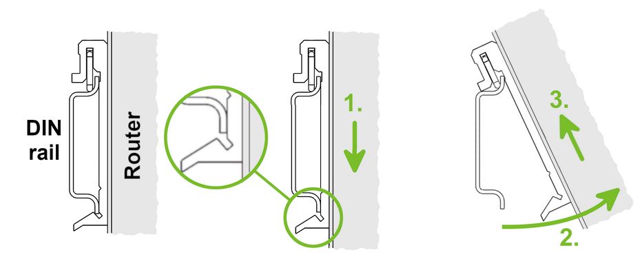
DIN Rail Mounting
Tips
The DIN rail clip is not included as a standard accessory. It can be ordered separately using order code BB-DIN-ICR32.
The DIN rail clip is suitable for DIN rails compliant with EN 60715 only. The default clip position varies by router series and is shown below.
Tips
ICR-2000 and ICR-2400 series:
Tips
ICR-2500 and ICR-2600 series:

Warning
Tighten the DIN rail clip screws to a maximum torque of 0.4 Nm.
To remove the router:
- Push down lightly on the router until the bottom part of the DIN rail clip disengages from the rail.
- Tilt the bottom part of the router away from the rail to release it.