Hardware and Connectivity
Refer to the Hardware Components section for a detailed summary of the product’s hardware.
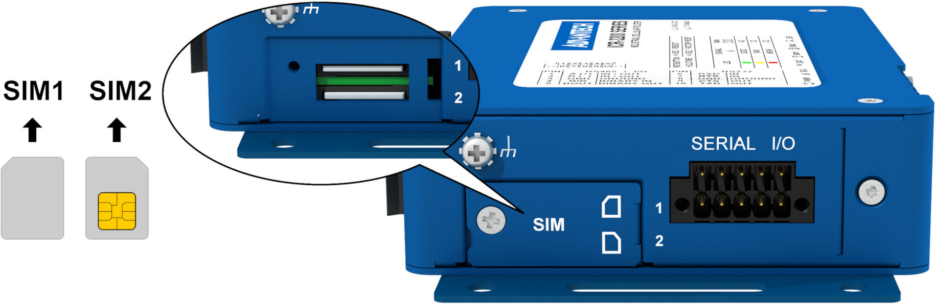
SIM Card Slots
The router includes slots for two Mini SIM cards (2FF; 25.0 x 15.0 x 0.76 mm), located beneath a metal cover. If the router is used for cellular communication, insert an activated SIM card with data enabled into the SIM card reader.
Dual SIM Feature: You can install two SIM cards simultaneously to use the dual SIM switching feature. Each SIM card can be configured with a unique Access Point Name (APN).
SIM Card Handling Procedure:
- Disconnect the router from the power supply.
- Unscrew and remove the SIM card cover.
- To remove a SIM card, use a spudger or your fingernail to press the card slightly into the slot until it clicks. Release it to eject.
- To insert a SIM card, push it into the slot until it clicks into place.
- Replace and secure the SIM card cover with screws.
- If required, enter the SIM PIN in the web interface (Administration → Unlock SIM Card).
Antenna Connections
For optimal performance, connect the appropriate antennas as follows:
| Order Code | Cellular (SMA) | GNSS (SMA) | WiFi (RP-SMA) |
|---|---|---|---|
| ICR-3201 | – | – | – |
| ICR-3201W | – | – | WIFI1, WIFI2 |
| ICR-3211B | ANT | – | – |
| ICR-3231 | ANT, DIV | GNSS | – |
| ICR-3231W | ANT, DIV | GNSS | WIFI1, WIFI2 |
| ICR-3232 | ANT, DIV | GNSS | – |
| ICR-3232W | ANT, DIV | GNSS | WIFI1, WIFI2 |
| ICR-3241 | ANT, DIV | GNSS | – |
| ICR-3241W | ANT, DIV | GNSS | WIFI1, WIFI2 |
Warning
- Operate the router only with a cellular antenna connected to the main antenna connector to avoid damage from reflected transmission energy.
- The WiFi2 connector also supports Bluetooth antennas.
- For optimal MIMO DL functionality, connect the diversity antenna to the DIV SMA connector.
- Ensure a tightening torque of 0.9 Nm when attaching antennas.
Bluetooth Support
The WiFi2 connector is compatible with Bluetooth antennas. For detailed Bluetooth specifications, refer to Bluetooth Parameters. The router’s Bluetooth support is divided into three components:
- Kernel Support and Drivers: Integrated from firmware version 6.2.6, this includes kernel-level Bluetooth support and necessary drivers.
- Bluetooth Router Application with BlueZ: This application, featuring the BlueZ Linux Bluetooth stack, enhances the router’s Bluetooth capabilities and is not pre-installed. To use this feature, download the Bluetooth Router App and install it manually.
- Node-RED Applications: For advanced Bluetooth capabilities, Node-RED and its Bluetooth node can be used. Like the Bluetooth Router App, Node-RED and the Node-RED Bluetooth Node are not pre-installed and must be installed manually.
Ethernet Interfaces
The router features two Ethernet interfaces (ETH0 and ETH1), accessible via RJ45 panel sockets. The pinout and signal descriptions are as follows:
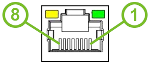
| Pin | Signal Mark | Description |
|---|---|---|
| 1 | Tx+ | Transmit Data+ (positive pole) |
| 2 | Tx- | Transmit Data- (negative pole) |
| 3 | Rx+ | Receive Data+ (positive pole) |
| 4 | — | — |
| 5 | — | — |
| 6 | Rx- | Receive Data- (negative pole) |
| 7 | — | — |
| 8 | — | — |
Tips
Ethernet ports are isolated from the ground with a barrier of 1500 V.
Power Supply and Grounding
The router operates on a DC power supply with a voltage range of +9 V to +36 V. A two-pin terminal connector (3.5 mm pitch) is included as standard. The power source must supply a peak current of 1.2 A. The router must be powered by a supply classified as a Limited Power Source (LPS) or CEC/NEC Class 2.
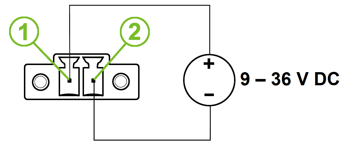
| Pin number | Signal mark | Description |
|---|---|---|
| 1 | VCC(+) | Positive pole of DC supply voltage (+9 to +36 V DC) |
| 2 | GND(-) | Negative pole of DC supply voltage |
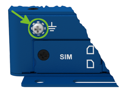
Warning
- Use the grounding screw on the left panel to ground the router. Ensure the negative pole of the DC power supply shares the same voltage reference as the grounding screw.
- A voltage difference between the grounding point and the negative pole may damage the router.
Low Power Mode (LPM)
Warning
In applications requiring low power consumption, such as solar power (not 24/7 operation), use LPM before powering down the entire router.
LPM minimizes power consumption by placing the router in a sleep state. Activate LPM using the lpm command. Wake the router from LPM using the BIN0 input or after a preset duration. Refer to the Command Line Interface application note for detailed instructions.
Grounding
All metal parts, including the box, are connected together with the negative pole of the power supply (common pole). Use the grounding screw on the left panel to ground the router.
Serial and IO Ports
The router’s RS232, RS485, and I/O interfaces are accessible via a 10-pin panel socket. Pinout details are as follows:
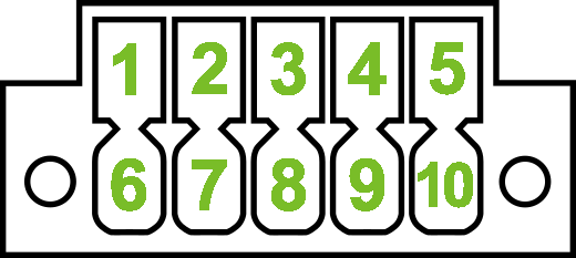
| Pin | Signal mark | Description |
|---|---|---|
| 1 | B (+) | In/Out |
| 2 | A (-) | In/Out |
| 3 | GND | Common |
RS485 Connection
| Pin | Signal mark | Description |
|---|---|---|
| 4 | DI0 | Digital Input |
| 5 | DO0 | Digital Output |
I/O Connection
| Pin | Signal mark | Description |
|---|---|---|
| 6 | RxD | In |
| 7 | CTS | In |
| 8 | GND | Common |
| 9 | RTS | Out |
| 10 | TxD | Out |
RS232 Connection
Tips
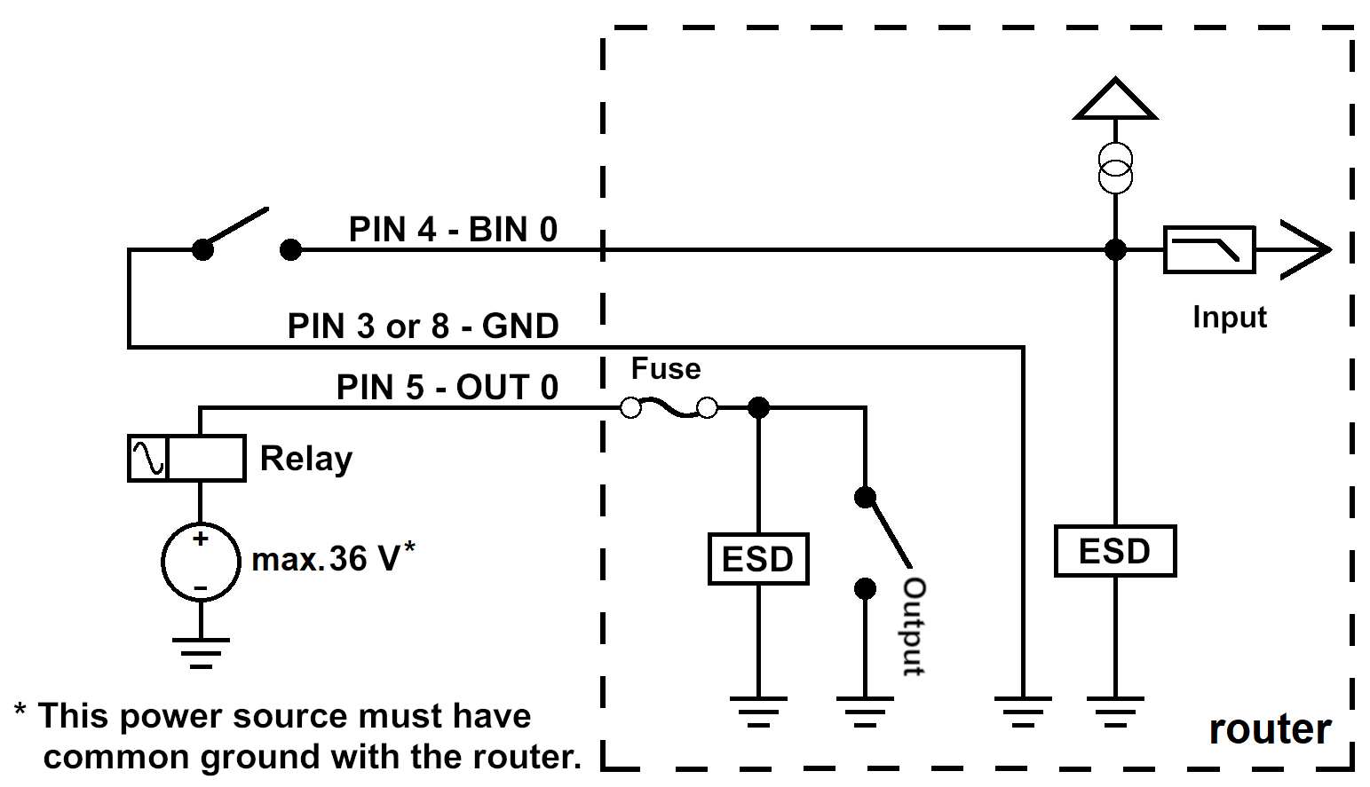
- Use external termination resistors to reduce noise and signal reflections.
- The maximum digital output load is 36 V at 500 mA.
The figure below shows the functional connection scheme for the digital input and output.
LED Indicators
The front panel includes the following status LEDs. On LAN-only models (ICR-3201, ICR-3201W), the SIG, DAT, and SIM indicators are not present.
| Symbol | Caption | Color | State | Description |
|---|---|---|---|---|
| PWR | Green | On | Starting the router. | |
| Green | Blinking | Router is ready (heartbeat). | ||
| Green | Fast blinking | Firmware upgrade in progress. | ||
| SIG | Green | On | Good signal (>66%). | |
| Orange | On | Fair signal. | ||
| Red | On | Poor signal (<33%). | ||
| DAT | Green | Blinking | Cellular network data transmission. | |
| SIM1 SIM2 | Green | Blinking | Waiting for data connection. | |
| Green | On | Connected via 4G technology. | ||
| Orange | On | Connected via 3G technology.¹ | ||
| Red | On | Connected via 2G technology.² | ||
| Red | Fast blinking | SIM card issue (missing card or PIN not entered). | ||
| USR | Green | Controlled by the user. | ||
| ETHx | Green | On | 100 Mbps selected. | |
| Green | Off | 10 Mbps selected. | ||
| Yellow | On | The network cable is connected. | ||
| Yellow | Blinking | Data transmission via Ethernet. | ||
| Yellow | Off | The network cable is disconnected. |
¹ Not applicable to ICR-3211B (Cat-M1 module — no 3G).
² Not applicable to ICR-3241 (NAM region).
Reset Options
The RST button has multiple functions. For details, refer to Initial Configuration → Reset.
Tips
Use a narrow screwdriver or a small tool to press the RST button.