Ethernet
To enter the Local Area Network configuration, select the Ethernet menu item in the Configuration section. The Ethernet item will expand in the menu on the left, allowing you to choose the appropriate Ethernet interface to configure: ETH0 for the first Ethernet interface and ETH1 for the second Ethernet interface.
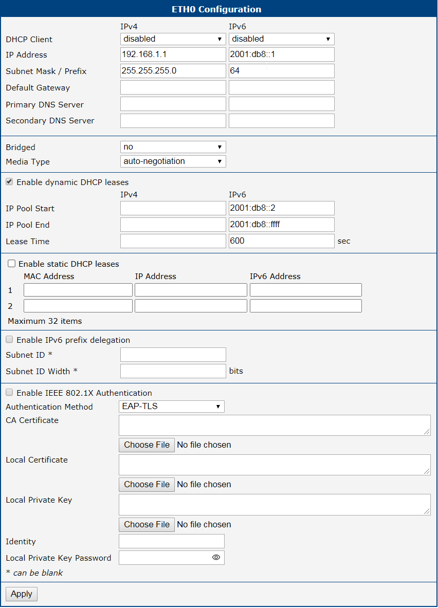
The LAN Configuration page is divided into IPv4 and IPv6 columns, as shown in Figure below. There is dual stack support for IPv4 and IPv6 protocols, meaning they can run concurrently. You can configure either one of them or both. If both IPv4 and IPv6 are configured, network devices will automatically select the communication protocol. The configuration items and differences between IPv6 and IPv4 are described in the tables below.
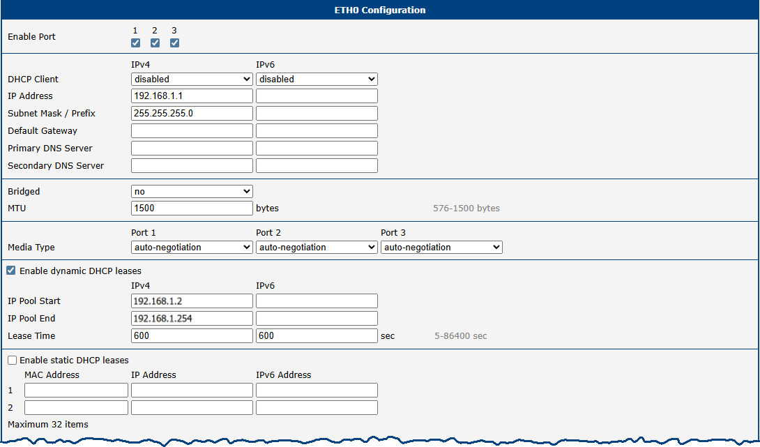
Since the ETH0 interface is a switched Ethernet interface with three ports, there are three checkboxes on the page labeled Enable Port. These can be used to enable or disable individual ports. Unlike a single-port Ethernet interface, this configuration page also includes a section for VLAN filtering settings; for more information, see VLAN Filtering below.
| Item | Description |
|---|---|
| Enable Port | Enables or disables the physical Ethernet port. |
| DHCP Client | Enables or disables the DHCP client function. If in the IPv6 column, the DHCPv6 client is enabled. The DHCPv6 client supports all three methods of obtaining an IPv6 address: SLAAC, stateless DHCPv6, and stateful DHCPv6. Options: • disabled: The router does not allow automatic allocation of an IP address from a DHCP server in the LAN network. • enabled: The router allows automatic allocation of an IP address from a DHCP server in the LAN network. |
| IP Address | A fixed IP address for the Ethernet interface. Use IPv4 notation in the IPv4 column and IPv6 notation in the IPv6 column. Shortened IPv6 notation is supported. |
| Subnet Mask / Prefix | Specifies the subnet mask for the IPv4 address. In the IPv6 column, fill in the prefix for the IPv6 address: a number in the range of 0 to 128. |
| Default Gateway | Specifies the IP address of the default gateway. If provided, every packet with a destination not found in the routing table is sent to this IP address. Use the correct IP address notation in both the IPv4 and IPv6 columns. |
| Primary DNS Server | Specifies the primary IP address of the DNS server. When the IP address is not found in the routing table, the router forwards the request to the DNS server specified here. Use the correct IP address notation in both the IPv4 and IPv6 columns. |
| Secondary DNS Server | Specifies the secondary IP address of the DNS server. |
The Default Gateway and DNS Server items are only used if the DHCP Client is set to disabled and if the ETH0 or ETH1 LAN is selected by the Backup Routes system as the default route. Since FW 5.3.0, Default Gateway and DNS Server are also supported on bridged interfaces (e.g., eth0 + eth1).
The following three items (in the table below) are global for the configured Ethernet interface. Only one bridge can be active on the router at a time. The DHCP Client, IP Address, and Subnet Mask / Prefix parameters of only one of the interfaces are used for the bridge. The ETH0 LAN has higher priority when both interfaces (ETH0 and ETH1) are added to the bridge. Other interfaces can be added to or removed from an existing bridge at any time. The bridge can be created on demand for such interfaces, but not if it is configured by their respective parameters.
Warning
Under certain conditions, the ETH interface may operate as a WAN interface, and the rules defined in the Firewall settings will be applied to it. Details are described in Backup Routes and are demonstrated with examples provided there.
| Item | Description |
|---|---|
| Bridged | Activates or deactivates the bridging function on the router. • no: The bridging function is inactive (default). • yes: The bridging function is active. See the Bridge Notes below the table for further details. |
| MTU | Maximum Transmission Unit value. Default value is 1500 bytes. |
| Media Type | Specifies the type of duplex and speed used in the network. • Auto-negotiation: The router automatically sets the best speed and duplex mode of communication according to the network's possibilities. • 100 Mbps Full Duplex: The router communicates at 100 Mbps, in the full duplex mode. • 100 Mbps Half Duplex: The router communicates at 100 Mbps, in the half duplex mode. • 10 Mbps Full Duplex: The router communicates at 10 Mbps, in the full duplex mode. • 10 Mbps Half Duplex: The router communicates at 10 Mbps, in the half duplex mode. |
Bridge Notes
A bridge behaves like a network switch, forwarding packets between interfaces that are connected to it. The Advantech router supports creating a bridge network within Ethernet interfaces or between Ethernet interfaces and Wi-Fi Access Point (AP) interfaces. Once the bridge is configured and established, a new interface named br0 is created. This interface will appear in the Status → Network → Interfaces section.
If a bridge is configured on two Ethernet interfaces, the br0 interface will inherit the IP address of the Ethernet interface with the lower index. IP address and subnet configuration of the Ethernet interface with the higher index will be removed. This behavior is consistent regardless of the order in which the interfaces are configured.
To include a Wi-Fi AP interface in the bridge, at least one Ethernet interface must also be part of the bridge configuration. In this case, the IP address of the bridge interface br0 will again be determined by the Ethernet interface (or interfaces) with the lowest index.
DHCP Server
The DHCP server assigns the IP address, gateway IP address (IP address of the router) and IP address of the DNS server (IP address of the router) to the connected clients. If these values are filled in by the user in the configuration form, they will be preferred.
The DHCP server supports static and dynamic assignment of IP addresses. Dynamic DHCP assigns clients IP addresses from a defined address space. Static DHCP assigns IP addresses that correspond to the MAC addresses of connected clients.
Info
- If IPv6 column is filled in, the DHCPv6 server is used. DHCPv6 server offers stateful address configuration to connected clients. Only when the Subnet Prefix above is set to 64, the DHCPv6 server offers both: the stateful address configuration and SLAAC (Stateless Address Autoconfiguration).
- For DHCPv6 static address assignment to work, DHCPv6 client must use DUID-LL or DUID-LLT types that are derived from its MAC address.
Warning
Do not to overlap ranges of static allocated IP addresses with addresses allocated by the dynamic DHCP server. IP address conflicts and incorrect network function can occur if you overlap the ranges.
Configuration of Dynamic DHCP Server
Item | Description |
|---|---|
| Enable dynamic DHCP leases | Select this option to enable a dynamic DHCP server. |
| IP Pool Start | Starting IP addresses allocated to the DHCP clients. Use proper notation in IPv4 and IPv6 column. |
| IP Pool End | End of IP addresses allocated to the DHCP clients. Use proper IP address notation in IPv4 and IPv6 column. |
| Lease time | Time in seconds that the IP address is reserved before it can be re-used. |
Configuration of Static DHCP Server
| Item | Description |
|---|---|
| Enable static DHCP leases | Select this option to enable a static DHCP server. You can define up to thirty-two rules. A new row for defining the next rule appears automatically after filling in the previous one. |
| MAC Address | MAC address of a DHCP client. |
| IPv4 Address | Assigned IPv4 address. Use proper notation. |
| IPv6 Address | Assigned IPv6 address. Use proper notation. |
IPv6 Prefix Delegation
Warning
This is an advanced configuration option. IPv6 prefix delegation works automatically with DHCPv6: use only if different configuration is desired and if you know the consequences.
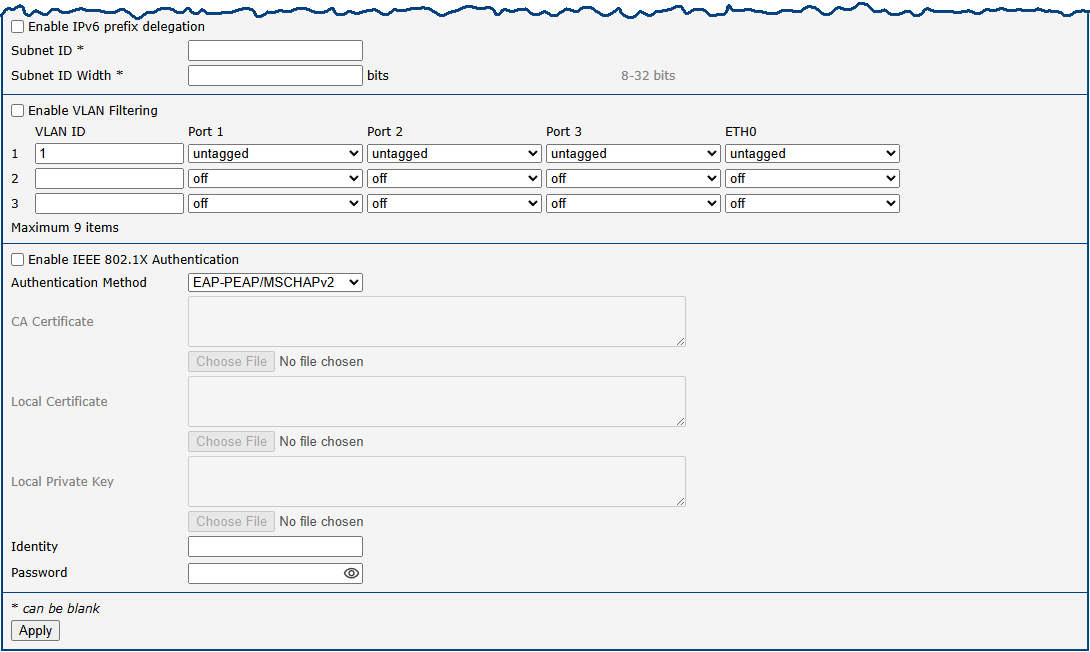
If you want to override the automatic IPv6 prefix delegation, you can configure it in this form. You have to know your Subnet ID Width (part of IPv6 address), see the figure below for the calculation help: it is an example: 48 bits is Site Prefix, 16 bits is Subnet ID (Subnet ID Width) and 64 bits is Interface ID.

| Item | Description |
|---|---|
| Enable IPv6 prefix delegation | Enables prefix delegation configuration filled-in below. |
| Subnet ID | The decimal value of the Subnet ID of the Ethernet interface. Maximum value depends on the Subnet ID Width. |
| Subnet ID Width | The maximum Subnet ID Width depends on your Site Prefix: it is the remainder to 64 bits. |
802.1X Authentication with RADIUS Server
IEEE 802.1X is an IEEE standard for port-based Network Access Control (PNAC). It provides an authentication mechanism for devices connecting to a LAN or WLAN using "EAP over LAN" (EAPoL), which encapsulates the Extensible Authentication Protocol (EAP).
IEEE 802.1X authentication involves three parties: a supplicant, an authenticator, and an authentication server, illustrated in the figure below.
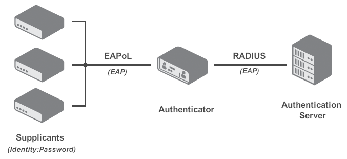
- The supplicant is a client device (e.g., a laptop) requesting network access.
- The authenticator is a network device (e.g., a switch or router) that controls network access and mediates communication with the authentication server.
- The authentication server (typically a RADIUS server) validates the supplicant's credentials and authorizes or denies access.
Info
Advantech routers can function as a supplicant or an authenticator, but not as an authentication server.
| Interface | Supplicant Role | Authenticator Role |
|---|---|---|
| LAN | As a built-in feature, configure LAN with 802.1X authentication. | While not a built-in feature, it can be facilitated by the 802.1X Authenticator Router App. |
| WiFi | In Station (STA) mode. | In Access Point (AP) mode. |
The 802.1X supplicant can be enabled in the section below. This requires configuring an identity and, for EAP-TLS, certificates.
| Item | Description |
|---|---|
| Enable IEEE 802.1X Authentication | Enables the 802.1X supplicant on this interface. |
| Authentication Method | Selects the authentication method (EAP-PEAP/MSCHAPv2 or EAP-TLS). |
| CA Certificate | Defines the CA certificate for the EAP-TLS protocol. |
| Local Certificate | Defines the local certificate for the EAP-TLS protocol. |
| Local Private Key | Defines the local private key for the EAP-TLS protocol. |
| Identity | The username (identity) for authentication. |
| Password | The password for authentication (used only for EAP-PEAP/MSCHAPv2). |
| Local Private Key Password | The password for the local private key (used only for EAP-TLS). |
Examples
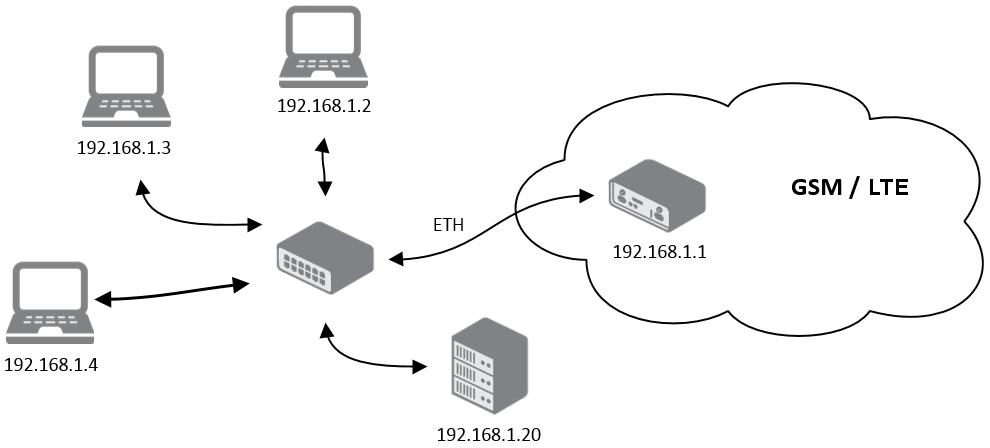
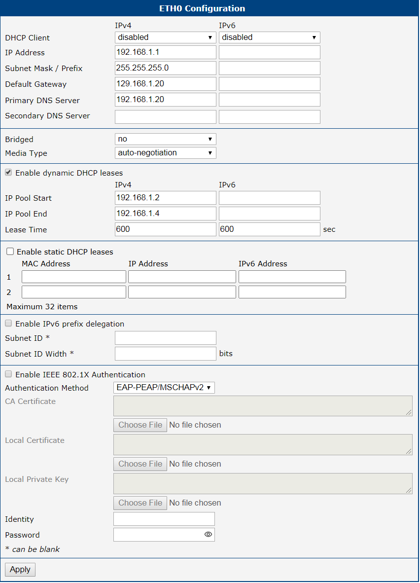
Example 1: IPv4 Dynamic DHCP Server, Default Gateway and DNS Server
- The range of dynamic allocated IPv4 addresses is from 192.168.1.2 to 192.168.1.4.
- The address is allocated for 600 second (10 minutes).
- Default gateway IP address is 192.168.1.20
- DNS server IP address is 192.168.1.20
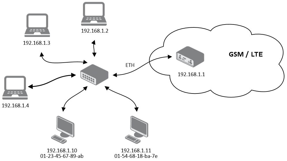
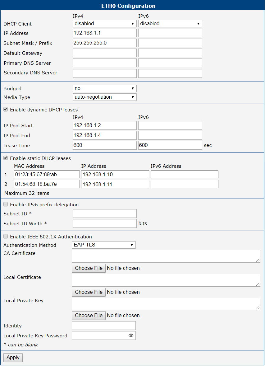
Example 2: IPv4 Dynamic and Static DHCP server
- The range of allocated addresses is from 192.168.1.2 to 192.168.1.4.
- The address is allocated for 600 seconds (10 minutes).
- The client with the MAC address 01:23:45:67:89:ab has the IP address 192.168.1.10.
- The client with the MAC address 01:54:68:18:ba:7e has the IP address 192.168.1.11.
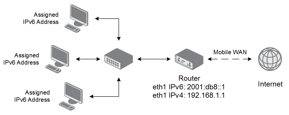
Example 3: IPv6 Dynamic DHCP Server
- The range of dynamic allocated IPv6 addresses is from 2001:db8
ffff. - The address is allocated for 600 second (10 minutes).
- The router is still accessible via IPv4 (192.168.1.1).
VLAN
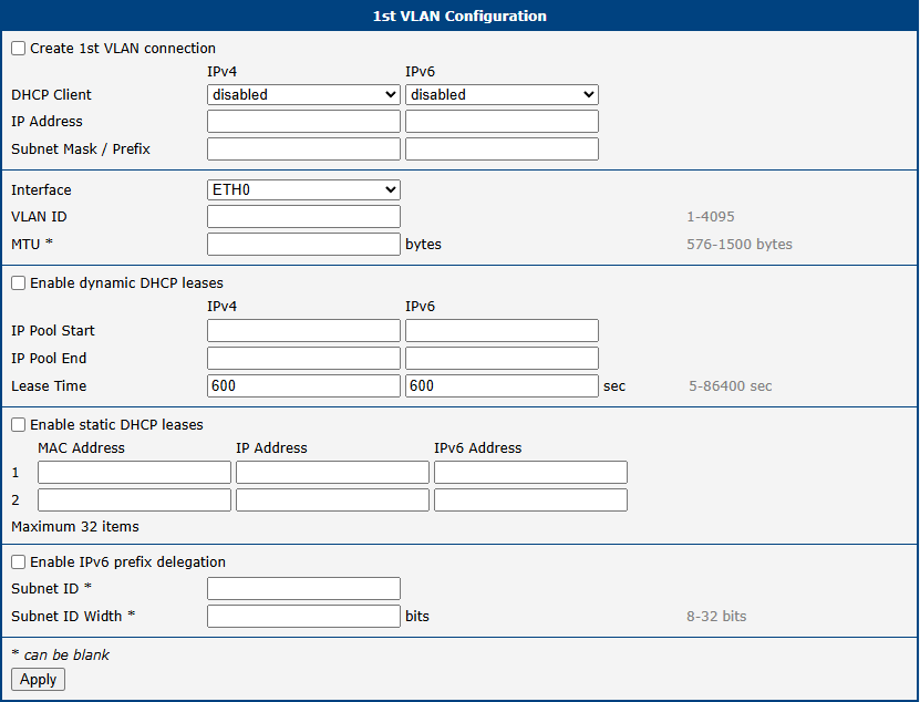
The router allows for the creation of up to three separate Virtual LAN (VLAN) interfaces, enabling network segmentation for enhanced security and traffic management. Each VLAN can be configured with its own IP address, DHCP server, and other network settings, effectively creating an independent logical network on a shared physical interface.
The VLAN configuration page, accessible via Configuration → VLAN, is divided into sections for interface setup, DHCP services, and IPv6 prefix delegation.
| Item | Description |
|---|---|
| Create VLAN connection | Enables the creation and configuration of this VLAN interface. |
| DHCP Client (IPv4/IPv6) | Enables or disables the DHCP client for the VLAN interface. When enabled, the interface will request an IP address from a DHCP server on the network. |
| IP Address | Assigns a static IPv4 or IPv6 address to the VLAN interface. |
| Subnet Mask / Prefix | Defines the subnet mask (for IPv4) or prefix length (for IPv6) for the static IP address. |
| Interface | Selects the parent physical Ethernet interface (ETH0 or ETH1) to which this VLAN will be bound. |
| VLAN ID | Specifies the unique identifier (1–4094) for the VLAN. This ID is used to tag traffic belonging to this virtual network. |
| MTU | Sets the Maximum Transmission Unit (MTU) in bytes for this VLAN interface. If left blank, the default value of the parent interface is used. |
| Enable dynamic DHCP leases | Enables the built-in DHCP server for this VLAN, which can dynamically assign IPv4 and IPv6 addresses to clients. • IP Pool Start: The first IP address in the DHCP assignment pool. • IP Pool End: The last IP address in the DHCP assignment pool. • Lease Time: The duration in seconds for which an IP address is leased to a client (default is 600). |
| Enable static DHCP leases | Enables static IP address assignments based on a client's MAC address. Up to 32 static leases can be defined for each address family (IPv4 and IPv6). • MAC Address: The hardware address of the client device. • IP Address: The fixed IPv4 address to be assigned to the client. • IPv6 Address: The fixed IPv6 address to be assigned to the client. |
| Enable IPv6 prefix delegation | Configures the router to request a block of IPv6 addresses from an upstream router, which can then be used to assign addresses to clients on this VLAN. • Subnet ID: The identifier for the requested subnet. • Subnet ID Width: The size of the subnet ID in bits. |
VRRP
The Virtual Router Redundancy Protocol (VRRP) is a standard network protocol that provides automatic default gateway redundancy. It creates a virtual router, represented by a shared floating IP address, which is managed by a primary (Master) router and one or more Backup routers. If the Master router fails, a Backup router automatically takes over its role, ensuring that devices on the LAN maintain network connectivity without manual intervention. This is particularly useful for adding cellular redundancy to a primary wired connection or for creating a high-availability setup between two cellular links.
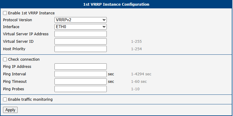
The router supports up to two VRRP instances, which can be configured on the Configuration → VRRP page.
VRRP Instance Configuration
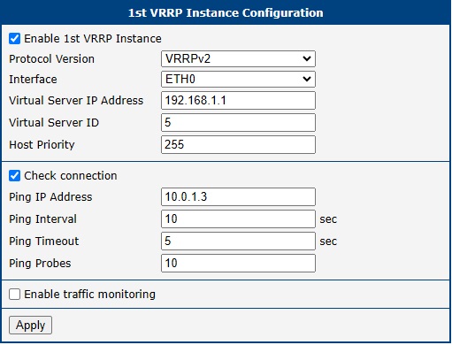
To enable and configure a VRRP instance, check the Enable VRRP box and configure the following parameters:
| Item | Description |
|---|---|
| Protocol Version | Specifies the VRRP version to be used. • VRRPv2: The original standard, widely supported, for IPv4 networks. • VRRPv3: The newer standard that adds support for IPv6 networks. |
| Interface | Selects the network interface (e.g., ETH0) on which VRRP advertisements will be sent and received. |
| Virtual Server IP Address | Sets the shared virtual IP address. This address must be identical for all routers in the VRRP group and serves as the default gateway for all LAN devices. |
| Virtual Server ID | Defines the identifier for the virtual router group. The range is 1–255. This ID must be identical for all routers participating in the same VRRP group. |
| Host Priority | Sets the priority value used to elect the Master router. The range is 1–254 (default is 100). • The router with the highest priority value becomes the Master. • If the Virtual Server IP matches the interface's real IP, the priority is automatically set to 255 (IP Address Owner), overriding this setting. |
Connection Checking
The Check connection feature adds a crucial layer of reliability by actively testing the health of the router's WAN connection. While VRRP itself detects router failures, this feature can detect upstream network outages even if the router is still running.
When enabled, the Master router periodically sends ICMP echo requests (pings) to a specified target IP address. If no replies are received after a configurable number of attempts, the router assumes the connection has failed and lowers its VRRP priority, triggering a failover to a Backup router.
Info
For reliable connection monitoring, ping a stable public IP address (e.g., a public DNS server like 8.8.8.8). In a private network, you can ping a remote gateway that is directly accessible or available via a VPN.
The Enable traffic monitoring option optimizes this process by suspending ping tests as long as any other traffic is received on the interface. This confirms the connection is active and reduces unnecessary data usage.
| Item | Description |
|---|---|
| Ping IP Address | The destination IP address for the ICMP echo requests. Domain names are not supported. |
| Ping Interval | The time in seconds between each ping request. |
| Ping Timeout | The time in seconds to wait for a response to each ping. |
| Ping Probes | The number of consecutive failed pings before the connection is declared down. |
Example
This example illustrates a high-availability topology using two routers, each with an independent cellular connection. For maximum redundancy, APN 1 and APN 2 are provided by different mobile operators.
- LAN Side: Both routers share the Virtual IP address 192.168.1.1 (Virtual Server ID 5). LAN clients use this IP as their default gateway, unaware of the physical routers.
- Priorities: The Main router (Real IP 192.168.1.2) is configured with a higher priority of 200, making it the Master. The Backup router (Real IP 192.168.1.3) has a lower priority of 100.
- WAN Side: To ensure end-to-end connectivity, both routers monitor a reliable public target (8.8.8.8) via their respective cellular WAN interfaces.
If the Main router fails to receive a ping response from 8.8.8.8, it automatically lowers its priority. The Backup router then becomes the new Master and takes over the Virtual IP, ensuring uninterrupted Internet access for all LAN clients.
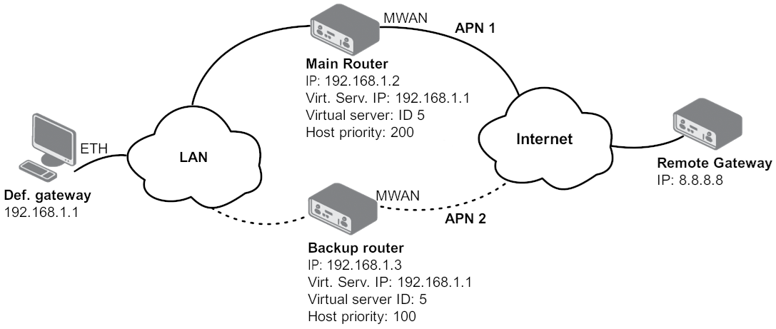
Configure the Backup router identically to the Main router, with one exception: set the Host Priority to 100. The Check connection settings should remain the same.
Mobile WAN
Select the Mobile WAN item in the Configuration menu to open the cellular network configuration page.
Connection to Mobile Network
Info
- Starting with firmware version 6.6.0, PLMN whitelisting is now an integrated firmware feature, available in the Operator field. This native functionality replaces the legacy PLMN Whitelist Router App.
- To avoid potential conflicts, disable or uninstall the legacy Router App before using the integrated PLMN whitelisting feature.
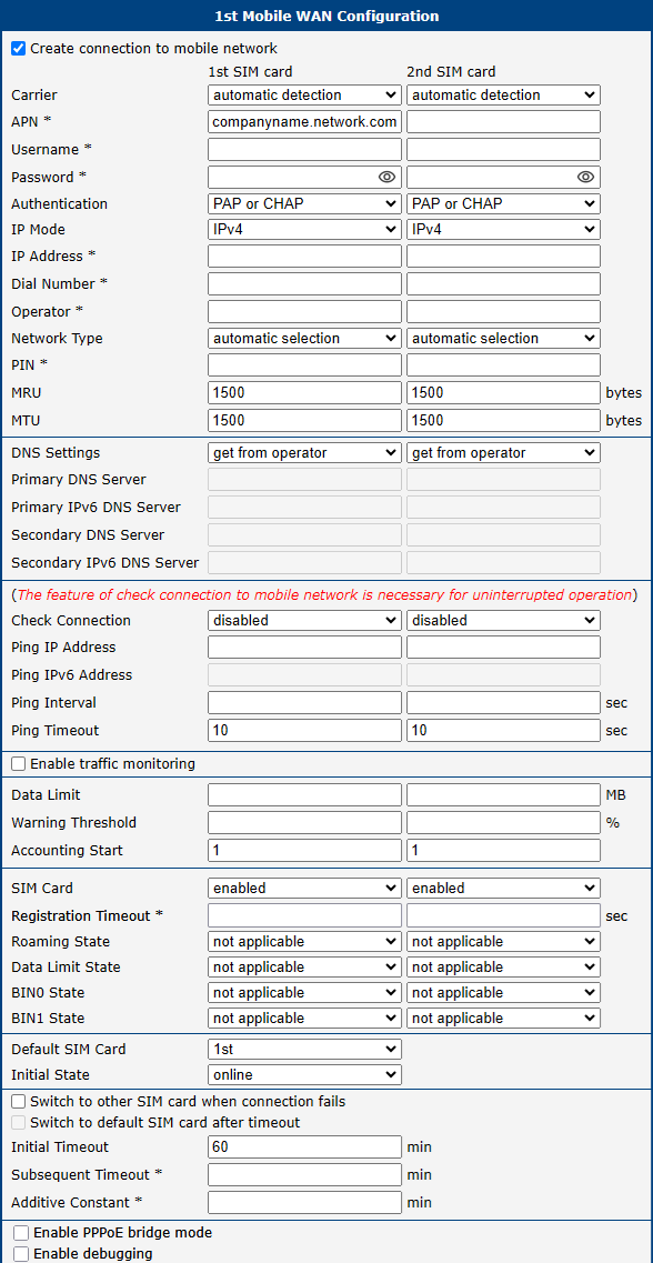
If the Create connection to mobile network checkbox is checked, the router will automatically attempt to establish a connection after booting up. You can specify the following parameters for each SIM card separately.
| Item | Description |
|---|---|
| Carrier | Allows for manual or automatic selection of a mobile network carrier. This is primarily available for global or NAM (North American) certified models. • For non-NAM models, the Outside North America option restricts connections to non-NAM operators. • For NAM-certified models, choices typically include: ◦ North America, Autoselect: Automatically detects and connects to a suitable NAM operator. ◦ North America, Generic: Enables a generic, PTCRB-compliant configuration. ◦ Manual selection of specific operators like AT&T, Rogers, T-Mobile, or Verizon. |
| APN | The Access Point Name (APN) of the mobile network. |
| Username | The username for logging into the mobile network. |
| Password | The password for logging into the mobile network. |
| Authentication | The authentication protocol used by the network. Both Username and Password must be specified for this setting to apply. • PAP or CHAP: The router automatically selects the authentication method. • PAP: Forces PAP authentication. • CHAP: Forces CHAP authentication. |
| IP Mode | The version of the IP protocol to be used. • IPv4: Use only the IPv4 protocol (default). • IPv6: Use only the IPv6 protocol. • IPv4/IPv6: Enable an independent dual stack for both IPv4 and IPv6. |
| IP Address | The IP address of the SIM card (for IPv4 and IPv4/IPv6 modes only). Enter this manually only if the carrier has assigned a static IP address. |
| Dial Number | The number the router dials for a CSD connection. The default is *99***1#. |
| Operator | Specifies the preferred mobile network operator using the carrier’s PLMN code. The behavior depends on the input: • Empty field: The router operates in automatic mode, connecting to any available network. • Single PLMN: The router locks to the specified operator and connects only to that network. • Comma-separated list (whitelist): The router scans for and connects to the first available operator from the list. • Whitelist with automatic fallback: Prefix the list with 0, (e.g., 0,23001,90001) to first connect automatically and then switch to a whitelisted operator if needed. |
| Network Type | Specifies the preferred mobile network technology. Available options depend on the router model and may include: automatic selection (never selects NB-IoT automatically), GPRS/EDGE, UMTS/HSPA, LTE, NB-IoT, LTE-M, and NR5G (5G SA). Note: 5G NSA (Non-Standalone) is a combination of LTE and 5G technologies and functions only when automatic selection is enabled. |
| PIN | The Personal Identification Number used to unlock the SIM card. Use this only if required by the SIM card. The card will be blocked after several failed attempts. |
| MRU | Maximum Receive Unit: the maximum packet size the router can receive. Default is 1500 B. Incorrect values may cause data reception errors. Minimum: 128 B for IPv4, 1280 B for IPv6. |
| MTU | Maximum Transmission Unit: the maximum packet size the router can transmit. Default is 1500 B. Incorrect values may cause data transmission errors. Minimum: 128 B for IPv4, 1280 B for IPv6. |
Info
- An incorrect MTU size may cause data transfer failures. A value that is too low increases fragmentation and overhead, while a value that is too high can cause packets to be dropped by the network.
- If the IP Address field is left blank, the carrier will automatically assign an IP address. Manual assignment can result in a faster connection.
- If the APN field is left blank, the router will attempt to auto-select an APN based on the SIM card’s IMSI. The selected APN name can be found in the System Log.
- To use a blank APN, enter the word
blankin the APN field.
Warning
An incorrect PIN will block the SIM card after several failed attempts.
Parameters marked with an asterisk (*) are required only if specified by your mobile network operator. If the router fails to connect, verify the accuracy of all entered data and consider trying a different authentication method or network type.
DNS Configuration
The DNS Settings parameter simplifies client-side configuration. When set to get from operator, the router automatically obtains the primary and secondary DNS server IP addresses from the carrier. To specify them manually, select set manually and enter the IPv4 or IPv6 addresses, depending on the selected IP Mode.
Network Connection Check
Warning
Enabling the Check Connection function is essential for ensuring uninterrupted operation of the router.
If Check Connection is set to enabled or enabled + bind, the router sends ping requests to the destinations specified in Ping IP Address or Ping IPv6 Address at regular intervals defined by Ping Interval. If you specify two addresses, the router considers the connection functional if at least one of the destinations responds; a connection failure is triggered only if both destinations are unreachable.
If a ping fails, a new one is sent after the Ping Timeout. If three consecutive pings fail, the router terminates and re-establishes the cellular connection. This monitoring function can be configured for each SIM card but runs only on the active SIM. Ensure you use reliable destination addresses, such as the operator’s DNS server or public DNS services.
If Check Connection is set to enabled, ping requests are sent based on the routing table and may use any available interface. To ensure pings are sent only through the mobile WAN interface, set it to enabled + bind. The disabled option deactivates connection checking.
Warning
For routers connected to the Verizon network, the connection retry interval increases with each attempt. The first two retries occur after 1 minute, followed by intervals of 2, 8, and 15 minutes. The ninth and all subsequent retries occur every 90 minutes.
If Enable Traffic Monitoring is checked, the router monitors Mobile WAN traffic instead of sending pings. If no data is transmitted, it will begin sending pings.
| Item | Description |
|---|---|
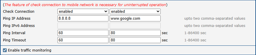
| Ping IP Address | The destination IPv4 address or domain name for ping queries. You can specify up to two comma-separated values. If two addresses are provided, the connection is considered failed only when neither responds. Available in IPv4 and IPv4/IPv6 modes. |
| Ping IPv6 Address | The destination IPv6 address or domain name for ping queries. You can specify up to two comma-separated values. If two addresses are provided, the connection is considered failed only when neither responds. Available in IPv6 and IPv4/IPv6 modes. |
| Ping Interval | The time interval between outgoing pings. |
| Ping Timeout | The time (in seconds) to wait for a ping response. |
Connection Check Example
The figure below shows a scenario where the IPv4 connection is monitored by pinging 8.8.8.8 every 60 seconds for the first SIM card and www.google.com every 80 seconds for the second SIM card. Since Enable traffic monitoring is active, pings are only sent if no other data traffic is detected.
Data Limit Settings
Info
The Data Limit parameters serve two independent functions:
- SMS Warning: Triggered based on the Warning Threshold. Requires the Send SMS when data limit is exceeded option to be enabled in Services → SMS.
- SIM Switching: To force the router to switch to another SIM once the limit is reached, the Data Limit State in the lower part of the form must be set to not exceeded. If left as not applicable, the limit is ignored for switching purposes.
| Item | Description |
|---|---|
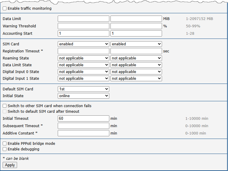
| Data Limit | The maximum amount of data (sent and received) allowed per billing period (one month). The maximum configurable value is 2 TB (2,097,152 MB). |
| Warning Threshold | A percentage of the Data Limit (ranging from 50% to 99%). When this threshold is exceeded, the router sends an SMS message. |
| Accounting Start | The day of the month when the billing cycle begins. The router starts counting data from this day. |
SIM Card Switching
In the lower part of the form, you can specify rules for switching between SIM cards.
Info
The router automatically switches between SIMs based on the logical AND of all configured rules (manual permission, roaming, data limit, and digital input state).
| Item | Description |
|---|---|
| SIM Card | Enables or disables the use of a SIM card. Setting all SIMs to disabled deactivates the cellular module. |
| Registration Timeout | Sets the registration timeout for the SIM card in seconds (default is 2 minutes). |
| Roaming State | Configures SIM usage based on roaming status (must be activated by your operator). • not applicable: Use the SIM everywhere. • home network only: Use the SIM only when not roaming. |
| Data Limit State | Configures SIM usage based on the data limit. • not applicable: Use the SIM regardless of the data limit. • not exceeded: Use the SIM only if the data limit has not been exceeded. |
| BINx State | Configures SIM usage based on digital input x state. • not applicable: Use the SIM regardless of the input state. • on: Use the SIM only if the input is on (voltage present). • off: Use the SIM only if the input is off (no voltage). |
Use the following parameters to specify the behavior of SIM card switching.
| Item | Description |
|---|---|
| Default SIM Card | Specifies the primary SIM card the router should use to connect. |
| Initial State | The action the module takes after a SIM is selected. • online: Establish a connection immediately (default). • offline: Remain offline. The state can be changed via SMS. The module also goes offline if no SIM card meets the switching criteria. |
| Switch to other SIM card when connection fails | If enabled, the router switches to the backup SIM card if the connection on the default SIM fails (as detected by the Check Connection feature). |
| Switch to default SIM card after timeout | If enabled, the router will attempt to switch back to the default SIM after a specified timeout. Applies only if the switch was triggered by a connection failure or roaming. Requires Switch to other SIM card when connection fails to be enabled. |
| Initial Timeout | The time (1 to 10,000 minutes) the router waits before the first attempt to switch back to the default SIM. |
| Subsequent Timeout | The time (1 to 10,000 minutes) the router waits after a failed attempt to switch back. |
| Additive Constant | An additional time (1 to 10,000 minutes) added to the Subsequent Timeout for each further attempt. |
Other Settings
| Item | Description |
|---|---|
| Enable PPPoE bridge mode | Enables PPPoE bridge mode on the Mobile WAN interface, allowing a device on the LAN to establish a direct PPPoE connection with the mobile operator and obtain the public IP address. |
| Enable debugging | Enables detailed diagnostic logging. For messages to appear in the system log, the Minimum Severity in Configuration → Services → Syslog must be set to Debug. Note: This can generate a large volume of data and should be disabled after troubleshooting. |
SIM Card Switching Examples
Example 1: Timeout Configuration
With Switch to default SIM card after timeout checked and the following values configured:
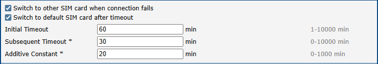
The first attempt to switch back to the default SIM occurs after 60 minutes. If it fails, the second attempt is made after 30 minutes. The third attempt follows after 50 minutes (30 + 20), and the fourth after 70 minutes (30 + 20 + 20).
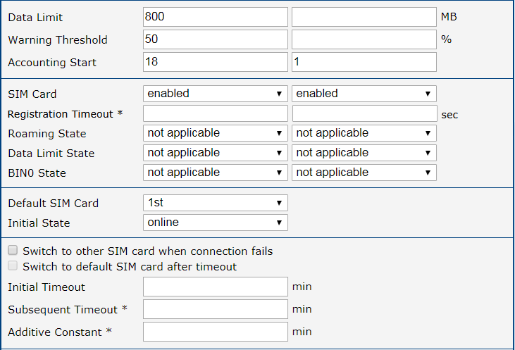
Example 2: Data Limit Switching
This example demonstrates how to configure the router to automatically switch to the second SIM card once the data limit of 800 MB is exceeded on the first (default) SIM. The Data Limit State for the 1st SIM card must be set to not exceeded. An SMS warning is also sent upon reaching 400 MB (50% threshold), which requires enabling the corresponding feature on the SMS Configuration page. The billing period starts on the 18th day of the month.
PPPoE
Point-to-Point Protocol over Ethernet (PPPoE) is a network protocol used to encapsulate PPP frames within Ethernet frames. It is commonly used to establish a connection with a broadband modem (e.g., ADSL) or other network device that acts as a PPPoE server. The router's PPPoE client allows it to authenticate and establish a session, after which it receives a public IP address and can forward traffic to the Internet.
The PPPoE settings are available on the Configuration → PPPoE page.
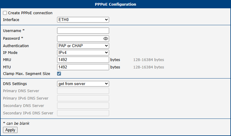
| Item | Description |
|---|---|
| Create PPPoE connection | Enables the PPPoE client on the selected interface. When checked, the router will automatically attempt to establish a connection on boot. |
| Interface | Selects the Ethernet interface (ETH0 or ETH1) on which the PPPoE client will operate. |
| Username | The username required for authentication with the PPPoE server. |
| Password | The password for the specified username. |
| Authentication | Specifies the authentication protocol to be used. • PAP or CHAP: Allows the router to negotiate and use either protocol (default). • PAP: Forces the use of Password Authentication Protocol. • CHAP: Forces the use of Challenge-Handshake Authentication Protocol. |
| IP Mode | Defines the IP protocol version for the connection. • IPv4: Establishes an IPv4-only session (default). • IPv6: Establishes an IPv6-only session. • IPv4/IPv6: Enables a dual-stack session for both IPv4 and IPv6. |
| MRU | The Maximum Receive Unit in bytes — the largest packet size the router can receive. The default is 1492 B. |
| MTU | The Maximum Transmission Unit in bytes — the largest packet size the router can transmit. The default is 1492 B. |
| Clamp Max. Segment Size | When enabled (default), automatically adjusts the TCP Maximum Segment Size (MSS) to prevent fragmentation, improving performance and reliability. |
| DNS Settings | Configures how DNS servers are obtained. • Get from server: Automatically uses the DNS servers provided by the PPPoE server (default). • Manual: Allows you to specify primary and secondary DNS servers manually. |
| Primary DNS Server | Primary IPv4 address of the DNS server. |
| Primary IPv6 DNS Server | Primary IPv6 address of the DNS server. |
| Secondary DNS Server | Secondary IPv4 address of the DNS server. |
| Secondary IPv6 DNS Server | Secondary IPv6 address of the DNS server. |
Warning
Setting an incorrect MTU or MRU value can lead to packet fragmentation or loss, resulting in a failed or unreliable connection. Use the default value of 1492 B unless your provider requires a different setting.
WiFi Access Point
Important Note on Upgrading to Firmware 6.6.0
When upgrading from a firmware version prior to 6.6.0, any separate Country settings for the Wi-Fi Access Point (AP) and Station (STA) modes will be consolidated into a single, unified Country setting. This change ensures regulatory compliance and simplifies configuration.
Info
The router supports configuring two separate WLANs (multiple SSIDs) for access point 1 (AP1) and access point 2 (AP2). However, both access points must share the same radio settings (channel, mode, channel width, etc.).
The router supports operating as both an access point (AP) and a station (STA) simultaneously.
RADIUS (Remote Authentication Dial-In User Service) is supported as a networking protocol for centralized authentication, authorization, and accounting (AAA). The router acts only as a RADIUS client, communicating with an external RADIUS server.
To enable Wi-Fi access point mode, check the Enable Wi-Fi AP box at the top of the Configuration → WiFi → Access Point 1 or Access Point 2 configuration page. In this mode, the router operates as an access point, allowing other devices in station (STA) mode to connect.
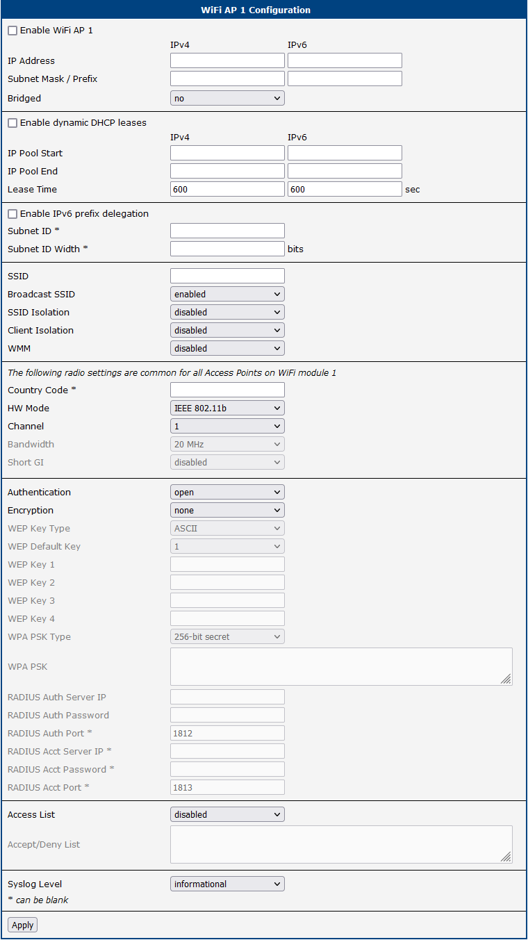
| Item | Description |
|---|---|
| Enable WiFi AP | Enables the Wi-Fi access point (AP). Both Access Point 1 (AP1) and Access Point 2 (AP2) can be enabled and operated simultaneously. |
| Country | A single Wi-Fi country code applies to all AP and STA interfaces and is configured on a separate page (accessible via the Change button). After changing the country, you must review the HW Mode, Bandwidth, and Channel settings. |
| IP Address | A fixed IP address for the Wi-Fi interface. Use standard IPv4 or IPv6 notation. |
| Subnet Mask / Prefix | Specifies the subnet mask for an IPv4 address or the prefix length (0 to 128) for an IPv6 address. |
| Bridged | Activates bridge mode: • no: Bridged mode is disabled (default). The WLAN is a separate network from the LAN. • yes: Bridged mode is enabled. The WLAN is connected to one or more LAN networks. In this mode, most network settings in this table are ignored, and the router uses the settings of the bridged LAN interface. See the Bridge Notes in Ethernet for further details. |
| Enable dynamic DHCP leases | Enables the dynamic allocation of IP addresses using the DHCP (or DHCPv6) server. |
| IP Pool Start | The start of the IP address range assigned to DHCP clients. |
| IP Pool End | The end of the IP address range assigned to DHCP clients. |
| Lease Time | The duration (in seconds) for which a client can use its assigned IP address. |
| Enable IPv6 prefix delegation | Enables prefix delegation for IPv6 clients. |
| Subnet ID | The decimal value of the Subnet ID for the interface. The maximum value is determined by the Subnet ID Width. |
| Subnet ID Width | The maximum Subnet ID width, which depends on your site's configuration. The remaining bits (up to 64) are used for the prefix. |
| SSID | The unique identifier (name) of the Wi-Fi network. Access Point 1 (AP1) and Access Point 2 (AP2) can have different SSIDs. |
| Broadcast SSID | Defines how the SSID is broadcast in the beacon frame: • enabled: The SSID is included in the beacon frame (standard behavior). • zero length: The SSID is omitted from the beacon frame. Requests to send beacon frames are ignored. • clear: SSID characters in the beacon are replaced with zeros, maintaining the original length. Requests for beacon frames are ignored. |
| SSID Isolation | When enabled with a selected zone, clients on this access point cannot communicate with clients on other access points that have a different zone selected. |
| Client Isolation | If enabled, clients connected to this access point are prevented from communicating with each other. If disabled, the AP functions like a switch, allowing clients on the same LAN to communicate. |
| WMM | Enables basic QoS (Quality of Service) for the Wi-Fi network. Suitable for simple applications that require QoS but does not guarantee network throughput. |
| Follow STA radio settings | When enabled, if the STA mode is connected to an external access point, the router's own AP radio settings will automatically adjust to match those of the external AP. |
| HW Mode¹ | Specifies the Wi-Fi standard supported by the access point. Available options include: IEEE 802.11b (2.4 GHz), IEEE 802.11b+g (2.4 GHz), IEEE 802.11b+g+n (2.4 GHz), IEEE 802.11a (5 GHz), IEEE 802.11a+n (5 GHz), IEEE 802.11ac (5 GHz). This setting is shared by both Access Point 1 and Access Point 2. |
| Bandwidth¹ | Selects the transfer bandwidth. This option may be unavailable for some hardware modes. If the selected bandwidth is occupied, the router may automatically switch to a lower bandwidth. This setting is shared by both Access Point 1 and Access Point 2. |
| Channel¹ | The channel on which the Wi-Fi access point operates. Available channels depend on the selected Country. Select Auto to allow the router to choose the optimal channel automatically. If you change the country, review this setting, as the previously selected channel may no longer be valid. This setting is shared by both Access Point 1 and Access Point 2. Note: When 40 MHz bandwidth is selected, in the 2.4 GHz band the channel number refers to the primary (20 MHz) channel; in the 5 GHz and 6 GHz bands, it refers to the center frequency of the 40 MHz channel. On NAM routers, only channels 1 to 11 are supported in the 2.4 GHz band. |
| Short GI | Available for 802.11n mode — enables a short guard interval (400 ns instead of 800 ns) to improve data transmission efficiency. This setting is shared by both Access Point 1 and Access Point 2. |
| Authentication | Defines the access control method for the Wi-Fi network: • open: [insecure] No authentication required. Encryption is not available.• shared: [insecure] Basic authentication with a WEP key.• WPA-PSK: [insecure] Pre-Shared Key authentication with WPA encryption.• WPA2-PSK: [insecure] Pre-Shared Key authentication with WPA2 encryption (AES).• WPA3-PSK: Simultaneous Authentication of Equals (SAE) with WPA3 encryption (AES). • WPA-Enterprise: [insecure] RADIUS-based authentication via an external server.• WPA2-Enterprise: RADIUS-based authentication with stronger encryption. • WPA3-Enterprise: RADIUS-based authentication with stronger encryption. |
| Encryption | Specifies the type of data encryption: • none: [insecure] No data encryption.• WEP: [insecure] Wired Equivalent Privacy.• TKIP: [insecure] Temporal Key Integrity Protocol, used for WPA.• AES: Advanced Encryption Standard, used for WPA2/WPA3. |
| WEP Key Type | Specifies the WEP key format: • ASCII: WEP key in ASCII format. • HEX: WEP key in hexadecimal format. |
| WEP Default Key | Specifies the default WEP key. |
| WEP Key 1–4 | Allows entry of up to four different WEP keys. • ASCII format: Must be enclosed in quotes. Supported lengths: 5 characters (40-bit), 13 characters (104-bit), 16 characters (128-bit). • Hexadecimal format: Supported lengths: 10 digits (40-bit), 26 digits (104-bit), 32 digits (128-bit). |
| WPA PSK Type | Specifies the format of the WPA Pre-Shared Key: • 256-bit secret: A 64-character hexadecimal key. • ASCII passphrase: A passphrase of 8 to 63 characters. • PSK File: Absolute path to a file containing key-MAC address pairs. |
| WPA PSK Secret | The secret key or passphrase for WPA-PSK authentication. |
| RADIUS Auth Server IP | The IPv4 or IPv6 address of the RADIUS authentication server. |
| RADIUS Auth Password | The access password for the RADIUS authentication server. |
| RADIUS Auth Port | The port number of the RADIUS authentication server (default is 1812). |
| RADIUS Acct Server IP | The IPv4 or IPv6 address of the RADIUS accounting server (if different from the authentication server). |
| RADIUS Acct Password | The access password for the RADIUS accounting server. |
| RADIUS Acct Port | The port number of the RADIUS accounting server (default is 1813). |
| Access List | Defines the mode of the client access list: • disabled: The access list is not used. • accept: Only clients in the list can access the network. • deny: Clients in the list are blocked from accessing the network. |
| Accept/Deny List | A list of client MAC addresses for network access control. Each MAC address should be entered on a new line. |
| Syslog Level | Defines the logging level for messages sent to the system log: • verbose debugging: The highest level of detail. • debugging • informational: The default level. • notification • warning: The lowest level. |
| Extra options | Allows the user to define additional parameters for hostapd. The options are appended to the configuration file. Use this feature only if you are familiar with its functionality. For more information, refer to the hostapd.conf configuration file. |
¹ The availability of configuration options may vary depending on the specific WiFi module and can be affected by the selected country code.
WiFi Station
Important Note on Upgrading to Firmware 6.6.0
When upgrading from a firmware version prior to 6.6.0, any separate Country settings for the Wi-Fi Access Point (AP) and Station (STA) modes will be consolidated into a single, unified Country setting. This change ensures regulatory compliance and simplifies configuration.
Info
You can find and connect to an available Wi-Fi network using Status → Wi-Fi → WiFi Scan.
The router supports operating as both an access point (AP) and a station (STA) simultaneously.
For networks using WPA-Enterprise security (RADIUS authentication), the station mode supports only the EAP-PEAP/MSCHAPv2 (both PEAPv0 and PEAPv1) and EAP-TLS authentication methods.
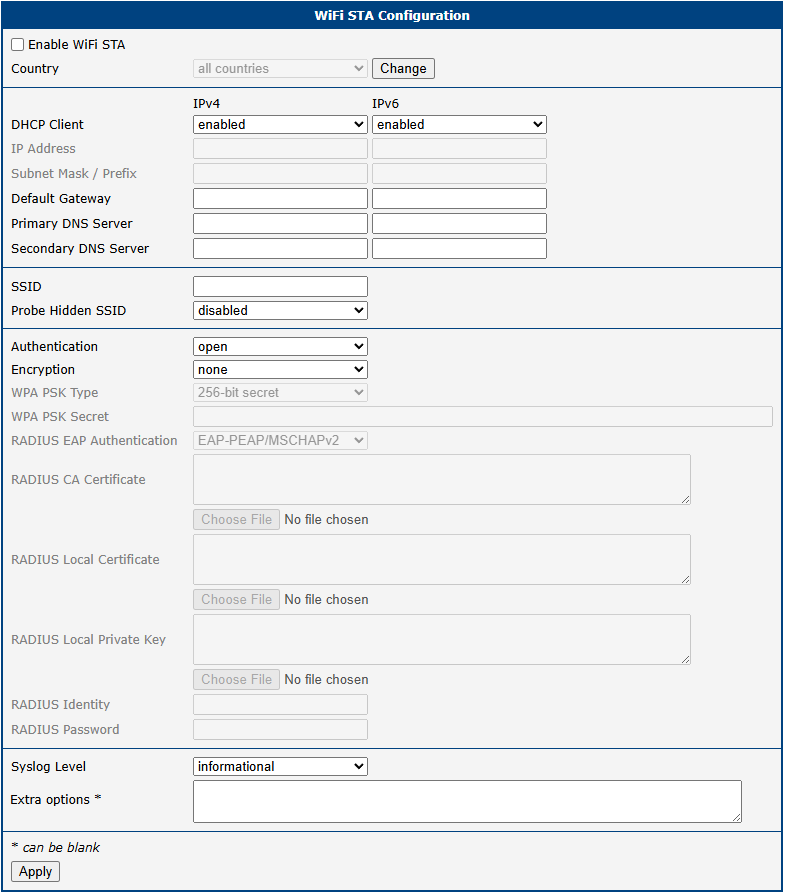
Activate Wi-Fi station mode by checking the Enable WiFi STA box at the top of the Configuration → WiFi → Station configuration page. In this mode, the router functions as a client station, connecting to an available access point (AP) and bridging its wired connection to the Wi-Fi network. In station mode, the Wi-Fi channel and bandwidth are determined by the associated access point.
| Item | Description |
|---|---|
| Enable WiFi STA | Enables the Wi-Fi station (STA) mode. |
| Country | A single Wi-Fi country code applies to all AP and STA interfaces and is configured on a separate page (accessible via the Change button). After changing the country, you must review your radio settings. |
| DHCP Client | Activates or deactivates the DHCP client (or DHCPv6 client for IPv6). |
| IP Address | Specifies a fixed IP address for the Wi-Fi interface. Use standard IPv4 or IPv6 notation. |
| Subnet Mask / Prefix | Defines the subnet mask for an IPv4 address or the prefix length (0 to 128) for an IPv6 address. |
| Default Gateway | Specifies the IP address of the default gateway. Packets with destinations not found in the routing table are sent to this gateway. |
| Primary DNS Server | Specifies the primary IP address of the DNS server. |
| Secondary DNS Server | Specifies the secondary IP address of the DNS server. |
| SSID | The unique identifier (name) of the Wi-Fi network to connect to. |
| Probe Hidden SSID | An access point with a hidden SSID does not broadcast its name, preventing the station from connecting automatically. Enable this option to force the station to probe for a specific hidden SSID. If you are not connecting to a hidden network, keep this disabled to reduce unnecessary radio transmissions. |
| Authentication | Access control methods for the Wi-Fi network: • open: [insecure] No authentication required.• shared: [insecure] Basic authentication with a WEP key.• WPA-PSK: [insecure] Authentication using a PSK with the WPA standard.• WPA2-PSK: [insecure] Authentication using a PSK with the WPA2 standard.• WPA3-PSK: Authentication using SAE with the WPA3 standard. • WPA-Enterprise: [insecure] Authentication using a RADIUS server with the WPA standard.• WPA2-Enterprise: Authentication using a RADIUS server with the WPA2 standard. • WPA3-Enterprise: Authentication using a RADIUS server with the WPA3 standard. |
| Encryption | The data encryption method: • none: [insecure] No encryption.• WEP: [insecure] Static encryption with WEP keys (may not be supported on some models).• TKIP: [insecure] Legacy dynamic encryption used with WPA/WPA2.• AES: Modern dynamic encryption used with WPA2/WPA3. |
| WPA PSK Type | The format of the key for WPA-PSK authentication: • 256-bit secret: A 64-character hexadecimal key. • ASCII passphrase: A passphrase of 8 to 63 characters. |
| WPA PSK Secret | The secret key or passphrase for WPA-PSK authentication. |
| RADIUS EAP Authentication | The EAP protocol used for RADIUS authentication: • EAP-PEAP/MSCHAPv2: Uses TLS to protect legacy EAP authentication. • EAP-TLS: Uses TLS for mutual authentication between the client and server. |
| RADIUS CA Certificate | The Certificate Authority (CA) certificate used to verify the server certificate during EAP-TLS authentication. |
| RADIUS Local Certificate | The client certificate required for EAP-TLS authentication. |
| RADIUS Local Private Key | The private key associated with the client certificate for EAP-TLS authentication. |
| RADIUS Identity | The identity (username) used to connect to the RADIUS server. |
| RADIUS Password | The password used to authenticate the RADIUS identity (for EAP-PEAP/MSCHAPv2). For EAP-TLS, this field is optional and specifies the decryption key for the local private key if it is encrypted. |
| Syslog Level | Defines the logging level for messages sent to the system log: • verbose debugging: The highest level of detail. • debugging • informational: The default level. • notification • warning: The lowest level. |
| Extra options | Allows the user to define additional parameters for wpa_supplicant. The options are appended to the configuration file. Use this feature only if you fully understand the implications. For more information, refer to the wpa_supplicant.conf configuration file. |
Backup Routes
The Backup Routes feature provides a mechanism for managing WAN connectivity, enabling automatic failover and load balancing across multiple Internet sources. The configuration is managed on the Configuration → Backup Routes page.
You can choose to let the router manage WAN connections automatically using its default priorities, or customize the behavior to meet specific network requirements.
Warning
- Some WAN interfaces (e.g., Wi-Fi, secondary Ethernet ports) may not be available on all router models.
- When using default priorities, an Ethernet interface will not be considered a valid WAN connection unless it has a static IP address configured or its DHCP client is enabled.
- In default priority mode, merely unplugging an Ethernet cable will not trigger a failover. The interface must be administratively down or fail to obtain an IP address.
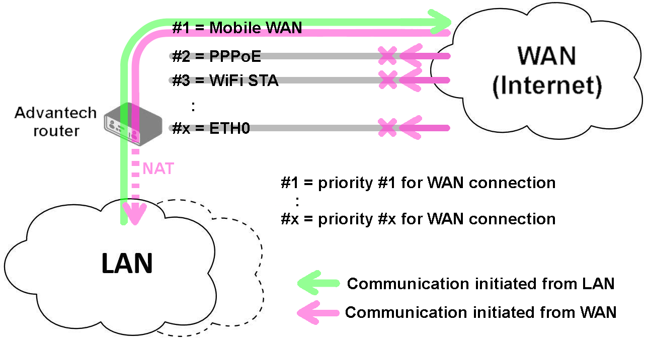
Default Failover
If the Enable backup routes switching option is unchecked, the router uses a predefined, internal priority list to select the active WAN interface. The default interface priority is as follows:
- Mobile WAN (
usb0orusb1) - PPPoE (
pppoe0) - Wi-Fi STA (
wlan0) - ETH1 (
eth1) - ETH0 (
eth0)
Based on this order, the router will only use the ETH1 interface if the Mobile WAN, PPPoE, and Wi-Fi connections are all unavailable. Note that a LAN interface (like ETH0) can become a WAN interface under certain conditions, which may have security implications. Ensure your firewall and NAT rules are configured accordingly.
Customized Backup Routes
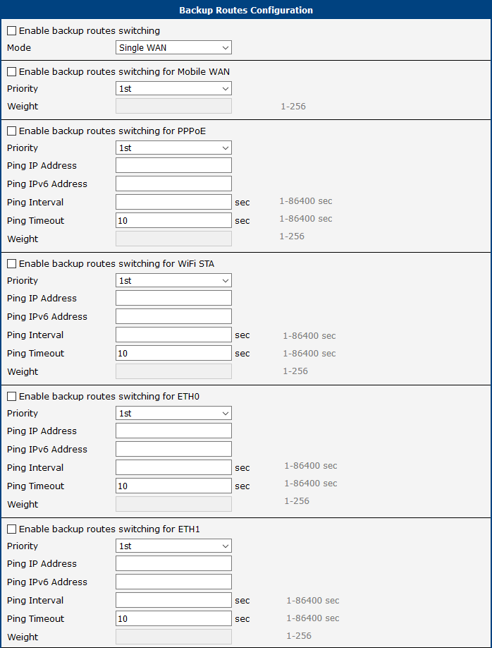
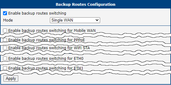
To gain full control over failover and load balancing, check the Enable backup routes switching box. This allows you to define interface priorities, connection checking parameters, and select one of three operational modes.
Operational Modes
| Item | Description |
|---|---|
| Mode | Selects the operational mode for managing WAN interfaces: • Single WAN: Only one WAN interface is active at a time. If the primary interface fails, the router switches to the next available interface by priority. The router is accessible from outside only on the active interface. • Multiple WANs: Same as Single WAN, with one difference: the router is accessible from outside on all enabled WAN interfaces simultaneously. • Load Balancing: Traffic is distributed across multiple WAN interfaces simultaneously. Assign a Weight to each interface to control its share of traffic streams. |
Interface Configuration
For each interface to include in the backup system, check its Enable backup routes switching box and configure the following parameters.
| Item | Description |
|---|---|
| Priority | Sets the priority of the interface (1st is highest). The router always uses the highest-priority active interface. |
| Ping IP Address | The destination IPv4 address or domain name for ICMP echo requests used to verify connection health. |
| Ping IPv6 Address | The destination IPv6 address or domain name for ICMP echo requests. |
| Ping Interval | The time in seconds between each ping test. |
| Ping Timeout | The time in seconds to wait for a response before considering a ping test failed. |
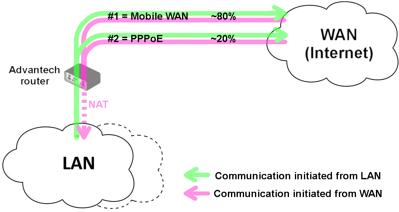
| Weight | (Load Balancing mode only) A value from 1 to 256 that determines the traffic ratio for this interface. For example, if two interfaces have weights of 4 and 1, they will handle approximately 80% and 20% of traffic streams, respectively. |
Warning
- Load Balancing: The traffic distribution is based on data streams, not total bandwidth. The actual data volume may not perfectly match the weight ratio, especially with a small number of concurrent connections.
- Mobile WAN: To use a cellular connection in a custom backup scenario, set Check Connection to enable + bind on the Mobile WAN configuration page.
Examples
Example 1: Default Settings
If no settings are configured on the Backup Routes page, the system operates with the default priorities. This provides a simple, automatic failover mechanism.
Note: Assume all affected interfaces are correctly configured and activated on their configuration pages.

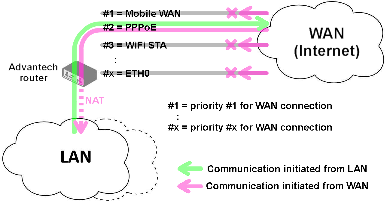
Example 2: Default Route Switching
This example shows how the default system handles a primary interface failure. If the highest-priority interface (Mobile WAN) becomes unavailable, the router automatically switches to the next interface in the default priority list (PPPoE).
Note: Assume all affected interfaces are correctly configured and activated on their configuration pages.
Example 3: Custom Backup Routes
This example demonstrates a custom failover configuration using the Mobile WAN, PPPoE, and ETH1 interfaces. The Mobile WAN is set as the highest priority, followed by PPPoE, and finally ETH1. The connection status of the PPPoE tunnel is monitored by pinging 172.16.1.1.
Note: Assume all affected interfaces are correctly configured and activated on their configuration pages.
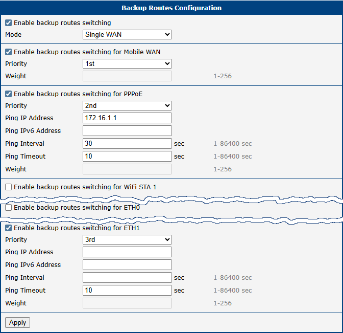
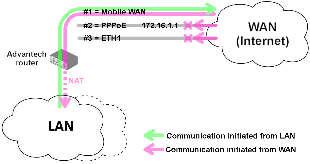
In Single WAN mode, if the Mobile WAN connection fails, the router fails over to the PPPoE tunnel.
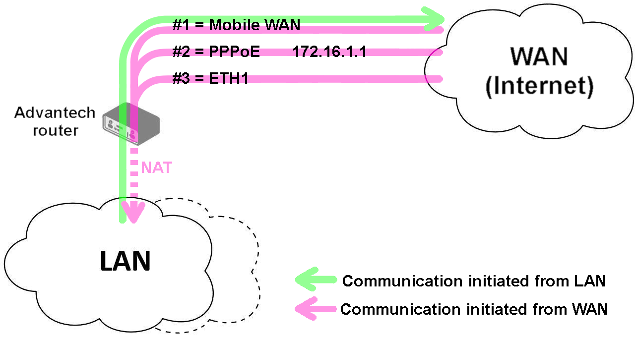
In Multiple WANs mode, the router is accessible via all three interfaces simultaneously, even though only one is used for outbound traffic at a time.
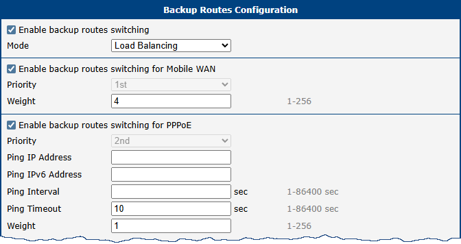
Example 4: Load Balancing Mode
This example shows a load balancing configuration between the Mobile WAN and a PPPoE interface. The weights are set to 4 and 1, respectively, meaning the Mobile WAN will handle approximately 80% of traffic streams and the PPPoE interface 20%.
Example 5: No WAN Routes
If Backup Routes is enabled but no interfaces are selected for WAN routing, the router has no dedicated WAN connection and functions as a LAN router. The Mobile WAN interface will not be used, even if connected to a cellular network.
Note: Assume all affected interfaces are correctly configured and activated on their configuration pages.
Static Routes
Static routes are manually configured, fixed paths that define how the router should forward traffic to a specific destination network or host. Unlike dynamic routes, which are learned automatically, static routes do not change unless they are manually updated. They are ideal for small, stable networks or for defining a specific path that must always be used.
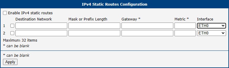
The configuration is managed on the Static Routes page. The router provides separate configuration tables for IPv4 and IPv6, each supporting up to thirty-two individual static routes. A new row is automatically added as you fill in the previous one.
| Item | Description |
|---|---|
| Enable IPv4 static routes | The master switch for the static routing feature. If unchecked, all static routes are disabled. Individual routes must also be enabled using the checkbox in their respective rows. |
| Destination Network | The IP address of the target network or host for which this route is being created. |
| Mask or Prefix Length | The subnet mask (for IPv4) or prefix length (for IPv6) of the destination network. |
| Gateway | The IP address of the next-hop router that will be used to reach the destination network. |
| Metric | A numerical value (1–255) representing the route's priority. A lower metric indicates a more preferred route. |
| Interface¹ | The network interface through which the specified gateway is reachable. |
¹ The Any option allows for the creation of routes where the gateway may not be directly connected, such as a GRE tunnel endpoint. When Any is selected, specifying a Gateway is mandatory, as it determines which interface will be used.
Firewall
The router's firewall allows you to control both incoming and outgoing IP traffic. The router supports independent IPv4 and IPv6 firewalls, including a dual-stack configuration for both protocols.
Understanding Firewall Zones
The router's firewall simplifies rule creation by grouping network interfaces into two logical zones based on their configured function: LAN (trusted) and WAN (untrusted). This assignment, not the interface name (e.g., eth1, wlan0), determines how the firewall treats its traffic.
- LAN Zone (Trusted): Contains all interfaces configured for your internal, local network. By default, this typically includes the Ethernet LAN ports (e.g.,
eth0,eth1) and any configured Wi-Fi Access Points (wlanX). - WAN Zone (Untrusted): Contains all interfaces configured to connect to external networks like the Internet. Common examples include the cellular module (
usb0), an Ethernet port re-configured for WAN use, or a Wi-Fi client (STA) connection (wlanX). For details on configuring backup WAN interfaces, refer to Backup Routes.
Default Behavior: By default, the firewall blocks all unsolicited incoming traffic from the WAN zone. Outbound traffic originating from the trusted LAN zone to the untrusted WAN zone is permitted. It is strongly recommended to review and customize the firewall rules to match your specific security requirements.
Clicking the Firewall item in the Configuration menu on the left expands it into three submenus: IPv4, IPv6, and Sites.
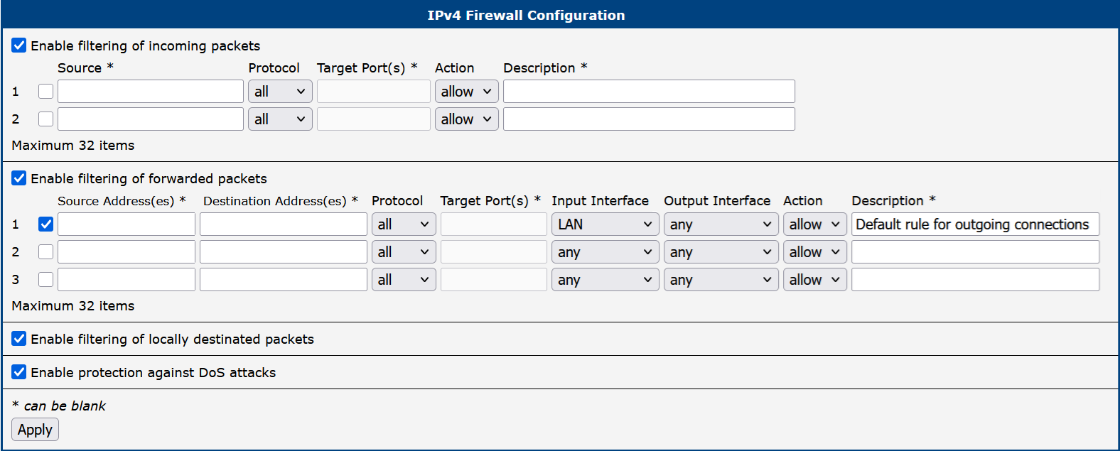
The figure below shows the default configuration page for the IPv4 firewall. The configuration fields are identical for both the IPv4 and IPv6 forms.
Info
Starting with firmware version 6.6.0, rule descriptions are stored directly as comments in the system's iptables configuration. This allows you to easily identify rules created via the web interface when managing the firewall from the command line (e.g., using iptables-save).
The first section of the configuration form defines the incoming firewall policy. If the Enable filtering of incoming packets checkbox is unchecked, all incoming connections are accepted. When enabled, and if connections originate from the WAN interface, the router checks them against the PREROUTING chain in the mangle table. The router accepts a connection only if a matching rule exists with the Action set to allow; otherwise, if no matching rule is found or the Action is set to deny, the connection is dropped.
You can define up to thirty-two rules based on IP addresses, protocols, and ports. Each rule can be enabled or disabled using the checkbox on the left of its row. A new row for the next rule appears automatically after filling in the previous one.
Please note that incoming rules apply only to connections originating from the WAN zone. For details on priority rules related to WAN interfaces, refer to Backup Routes.
| Item | Description |
|---|---|
| Source¹ | Specifies the IP address to which the rule applies. Use an IPv4 address in the IPv4 form and an IPv6 address in the IPv6 form. |
| Protocol | Specifies the protocol to which the rule applies: • all: The rule applies to all protocols. • TCP: The rule applies to the TCP protocol. • UDP: The rule applies to the UDP protocol. • GRE: The rule applies to the GRE protocol. • ESP: The rule applies to the ESP protocol. • ICMP/ICMPv6: The rule applies to ICMP (ICMPv6 for IPv6). |
| Target Port(s) | Specifies the port number or range. Enter a single port or a range separated by a hyphen (e.g., 1020–1040). |
| Action | Specifies the action the router performs: • allow: Permits the packets to enter the network. • deny: Blocks the packets from entering the network. |
| Description | A user-defined description for the rule, which is stored as a comment in iptables. |
¹ This field supports IP address input in the formats: IP, IP/mask, or IP_start-IP_end.
The next section defines the forwarding firewall policy. If the Enable filtering of forwarded packets checkbox is unchecked, all incoming packets are forwarded. When enabled, and if a packet is addressed to another network interface, the router processes it through the FORWARD chain in iptables. If the FORWARD chain accepts the packet, the router forwards it, provided there is a corresponding entry in the routing table.
You can define up to thirty-two forwarding rules. A new row appears automatically after filling in the previous one. The forwarding settings can be applied to specific interfaces, providing granular control over traffic flow.
Info
As shown in the figure above, the first entry in the IPv6 forwarded packets configuration is the default firewall rule for NAT64, which is disabled by default. To enable the NAT64 function, navigate to Configuration → NAT → IPv6 → Enable NAT64.
| Item | Description |
|---|---|
| Source Address(es)¹ | Specifies the source IP address to which the rule applies (IPv4 or IPv6). |
| Destination Address(es)¹ | Specifies the destination IP address to which the rule applies (IPv4 or IPv6). |
| Protocol | Specifies the protocol to which the rule applies: • all, TCP, UDP, GRE, ESP, ICMP/ICMPv6. |
| Target Port(s) | Specifies the target port number or range. |
| Input Interface | Specifies the interface on which the packet is received. Options include any, WAN zone, LAN zone, or specific interfaces such as Ethernet, Bridge, VLAN, Mobile, PPPoE, Wi-Fi, and VPN interfaces. |
| Output Interface | Specifies the interface through which the packet will be sent. The available options are the same as for Input Interface. |
| Action | Defines the action the router performs: • allow: Permits the packets to be forwarded. • deny: Blocks the packets from being forwarded. |
| Description | A user-defined description for the rule, which is stored as a comment in iptables. |
¹ This field supports IP address input in the formats: IP, IP/mask, or IP_start-IP_end.
When the Enable filtering of locally destined packets function is enabled, the router automatically drops packets requesting an unsupported service without sending any notification.
To protect against DoS (Denial of Service) attacks, the Enable protection against DoS attacks option limits the number of allowed connections per second to five. A DoS attack floods the target system with excessive requests, overwhelming its resources.
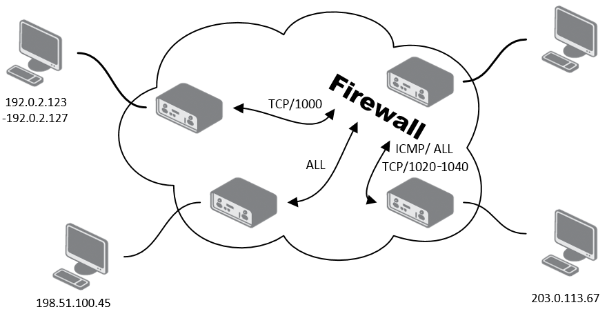
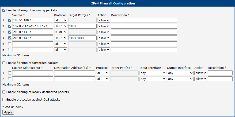
Firewall Configuration Example
In this example, the router is configured to permit the following access:
- Access from IP address 198.51.100.45 using any protocol.
- Access from the IP address range 192.0.2.123 to 192.0.3.127 using the TCP protocol on port 1000.
- Access from IP address 203.0.113.67 using the ICMP protocol.
- Access from IP address 203.0.113.67 using the TCP protocol on target ports ranging from 1020 to 1040.
See the network topology and configuration form in the figures below.
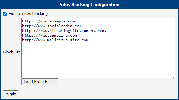
Sites
Info
This feature works only if the device is using the router as its DNS server.
On the Sites configuration page, you can define specific URLs that you want the firewall to block. To enable this feature, check the Enable sites blocking option.
You can then build your blocklist in two ways:
- Manually enter each URL into the Block list box, placing each one on a new line.
- Use the Load From File... button to import a predefined list of URLs from a plain text file.
NAT
Network Address Translation (NAT) is a fundamental networking function that modifies IP address information in packet headers while they are in transit. The router implements NAPT (Network Address and Port Translation), also known as PAT (Port Address Translation) or IP masquerading, which allows multiple devices in a private network to share a single public IP address.
The NAT configuration is managed on the Configuration → NAT page, which has separate subpages for IPv4 and IPv6.
Port Forwarding
Port forwarding, also known as destination NAT (DNAT), allows external devices to connect to a specific service on a device within the private LAN. You can define up to sixty-four port forwarding rules.
Item | Description |
|---|---|
| Public Port(s) | The external port or port range on the router's WAN interface. A single port or a range (e.g., 8000-8010) can be specified. |
| Private Port(s) | The internal port or port range on the destination server. |
| Type | The protocol for the rule: TCP or UDP. |
| Server IP Address | The private IPv4 or IPv6 address of the server on the LAN to which traffic will be forwarded. |
| Description | An optional description for the rule. |
For configurations requiring more than sixty-four rules, additional rules can be added to the startup script (Configuration → Scripts). Use the following iptables command format for IPv4:
For IPv4 NAT:
iptables -t nat -A pre_nat -p tcp --dport [PORT_PUBLIC] -j DNAT --to-destination [IPADDR]:[PORT_PRIVATE]For IPv6, use the ip6tables command:
ip6tables -t nat -A napt -p tcp --dport [PORT_PUBLIC] -j DNAT --to-destination [IP6ADDR]:[PORT_PRIVATE]Replace the bracketed values with your specific port numbers and IP addresses.
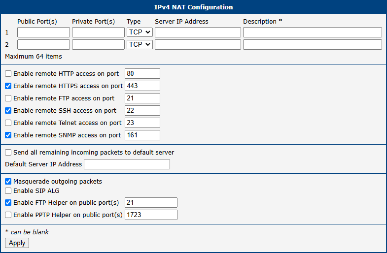
Remote Access
This section allows you to enable remote access to the router's own management services from the WAN interface.
Item | Description |
|---|---|
| Enable remote HTTP access on port | Enables remote access to the router's web interface via HTTP on the specified port. If the HTTP service is disabled in Services → HTTP while HTTPS is enabled, incoming requests on this port will be redirected to HTTPS. |
| Enable remote HTTPS access on port | Allows secure remote access to the router's web interface via HTTPS on the specified port. |
| Enable remote FTP access on port | Allows remote access to the router's FTP server on the specified port. |
| Enable remote SSH access on port | Allows remote access to the router's command-line interface via SSH on the specified port. |
| Enable remote Telnet access on port | Allows remote access to the router's command-line interface via Telnet on the specified port. |
| Enable remote SNMP access on port | Allows remote management and monitoring of the router via SNMP on the specified port. |
Warning
For secure management, always use HTTPS access. The HTTP remote access option is for redirection only. Exposing unsecured services to the Internet poses a significant security risk and should be avoided.
Default Server and NAT Helpers
This section contains advanced NAT features, including a default server (DMZ) setting and Application-Layer Gateways (ALGs) for specific protocols.
Item | Description |
|---|---|
| Send all remaining incoming packets to default server | When enabled, all incoming traffic from the WAN that does not match any other port forwarding rule is forwarded to the specified default server. This is often referred to as a DMZ. |
| Default Server Address | The private IPv4 or IPv6 address of the default server. |
| Enable NAT64 | (IPv6 only) Activates NAT64 translation, allowing IPv6-only clients to communicate with IPv4-only services. Requires a corresponding firewall rule to be effective. |
| Masquerade outgoing packets | Enables source NAT (SNAT) for all outgoing traffic, making it appear to originate from the router's public WAN IP address. This should almost always be enabled. |
| Enable SIP ALG | (IPv4 only) Enables the Session Initiation Protocol Application-Layer Gateway, which helps VoIP traffic traverse NAT by modifying SIP packet headers. |
| Enable FTP Helper on public port(s) | Assists with NAT traversal for the FTP protocol, particularly for active mode FTP, on the specified port (default is 21). |
| Enable PPTP Helper on public port(s) | (IPv4 only) Assists with NAT traversal for the Point-to-Point Tunneling Protocol (PPTP) for VPN connections on the specified port (default is 1723). |
Warning
The NAT64 functionality is based on the Jool implementation, which has certain limitations. It is not possible to connect to the router itself using its NAT64-mapped IPv4 address (e.g., 64:ff9b::192.0.2.1). Furthermore, firewall rules for NAT64 traffic must be created in the input chain, not the forward chain, as Jool processes the packets as if they originate from the router itself.
Examples
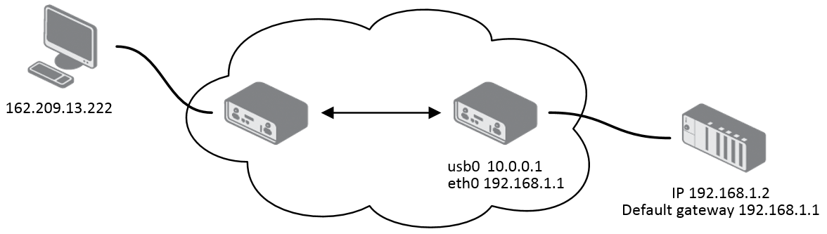
Example 1: Forward All Traffic to a Single Device (DMZ)
This configuration forwards all incoming traffic from the Internet to a single device on the LAN, effectively placing it in a Demilitarized Zone (DMZ).
- Enable the Send all remaining incoming packets to default server option.
- Enter the IP address of the target device in the Default Server IP Address field.
The LAN device must be configured to use the router's IP address as its default gateway. With this setup, a ping request to the router's public SIM card IP address will be answered by the device, not the router.
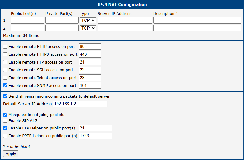
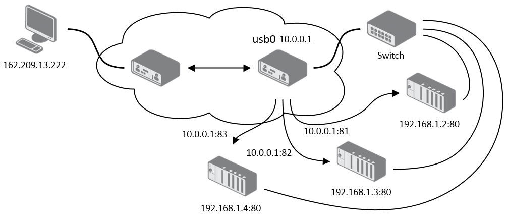
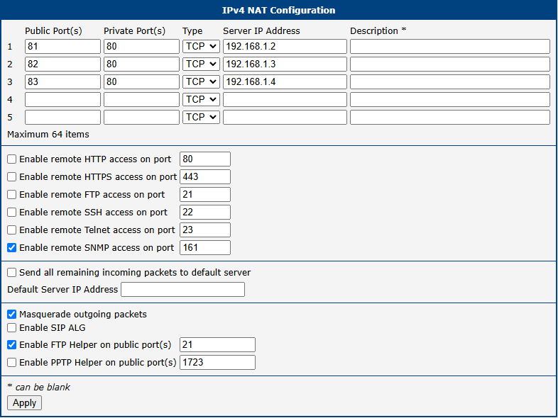
Example 2: Port Forwarding to Multiple Devices
This example shows how to make services on multiple internal devices accessible from the Internet using port forwarding. A different public port is mapped to a service on each internal server.
For instance, to make a web server on device 192.168.1.2 (port 80) accessible via public port 81, create the following rule:
- Public Port(s):
81 - Private Port(s):
80 - Type: TCP
- Server IP Address:
192.168.1.2
External users can then access the web server by navigating to http://<router_public_ip>:81. Since the Send all remaining incoming packets to default server option is disabled, any traffic not matching a specific rule will be dropped.
OpenVPN
OpenVPN is a robust and highly flexible VPN solution that creates secure point-to-point or site-to-site connections over the Internet. The router supports up to four concurrent OpenVPN tunnels, each with its own configuration. Both IPv4 and IPv6 are supported in a dual-stack configuration.
To configure an OpenVPN tunnel, select OpenVPN from the Configuration section of the main menu. The menu will expand to show configuration pages for each tunnel (1st Tunnel through 4th Tunnel).
Tunnel Configuration
The following table describes the available parameters for configuring an OpenVPN tunnel.
| Item | Description |
|---|---|
| Description | An optional name or description for the tunnel. |
| Interface Type | Determines the layer at which the VPN operates: • TUN (default): A routed VPN that operates at the network layer (Layer 3). This is the most common mode. • TAP: A bridged VPN that operates at the data link layer (Layer 2). This requires a bridge to be configured on the corresponding Ethernet interface. |
| Protocol | The transport protocol for the VPN tunnel: • UDP/UDPv6: Uses UDP for transport. This is generally faster and is the recommended default. • TCP/TCPv6 Server: Uses TCP and configures the router to act as a server, listening for incoming client connections. • TCP/TCPv6 Client: Uses TCP and configures the router to act as a client, initiating a connection to a remote server. |
| UDP/TCP Port | The port number for the selected protocol. The default is 1194. |
| 1st/2nd Remote IP Address | The IPv4 address, IPv6 address, or domain name of the remote OpenVPN server. A second address can be provided for redundancy. |
| Remote Subnet | The IPv4 address of the remote network behind the tunnel. |
| Remote Subnet Mask | The subnet mask of the remote IPv4 network. |
| Redirect Gateway | If enabled, all of the router's outbound traffic will be sent through the VPN tunnel. |
| Local/Remote Interface IP Address | The virtual IPv4 addresses for the local and remote endpoints of the tunnel interface. |
| Remote IPv6 Subnet | The IPv6 prefix of the remote network behind the tunnel. |
| Remote IPv6 Prefix | The prefix length of the remote IPv6 network. |
| Local/Remote Interface IPv6 Address | The virtual IPv6 addresses for the local and remote endpoints of the tunnel interface. |
| Ping Interval | The interval in seconds at which keep-alive packets are sent to the remote peer. |
| Ping Timeout | The time in seconds to wait for a response before considering the tunnel to be down. This value should be greater than Ping Interval. |
| Renegotiate Interval | The time in seconds before the session key is renegotiated. This applies to certificate-based authentication modes. |
| Max Fragment Size | The maximum size in bytes of a packet before it is fragmented. |
| Compression | Configures data compression for the VPN tunnel: • none (recommended): No compression is used. This is the most secure setting. • LZO (deprecated): Uses the legacy LZO lossless compression algorithm. This option is insecure due to the VORACLE vulnerability and is pending removal from future OpenVPN versions. Its use is strongly discouraged — it is provided only for backward compatibility with legacy systems. |
| NAT Rules | Determines whether NAT should be applied to traffic passing through the tunnel. |
Authentication and Security
OpenVPN offers multiple authentication methods, allowing for flexible and highly secure configurations.
| Item | Description |
|---|---|
| Authenticate Mode | Selects the method used to authenticate the VPN peers: • none: No authentication. Not recommended for production use. • pre-shared secret: Uses a static, pre-shared key for authentication. • username/password: Authenticates using a username, password, and a common CA certificate. • X.509 cert.: Uses a full PKI with certificates for authentication. Can be configured in client, server, or multi-client server mode. |
| Security Mode | Configures an additional HMAC layer for verifying control channel packets: • tls-auth: Authenticates control channel packets. • tls-crypt: Encrypts and authenticates control channel packets, providing better protection against DoS attacks. This is the recommended mode. |
| Pre-shared Secret | The static key used for Pre-shared secret authentication mode or as the HMAC key for Security Mode. |
| CA Certificate | The certificate of the Certificate Authority that signed the client and server certificates. |
| DH Parameters | The Diffie-Hellman parameters file, required for server-side X.509 configurations. |
| Local Certificate | The public certificate for this router. |
| Local Private Key | The private key corresponding to the local certificate. |
| Local Passphrase | The passphrase used to protect the local private key file. |
| Username/Password | The credentials used for the Username/password authentication mode. |
| Security Level | Sets the minimum cryptographic strength for the connection. Higher levels disable older, less secure algorithms. • 2 - Medium (default): Enforces a minimum of 112-bit security. • 3 - High: Enforces a minimum of 128-bit security (e.g., requires AES-128 or stronger). • 4 - Very High: Enforces a minimum of 192-bit security (e.g., requires AES-192 or stronger). |
| Extra Options | A field for adding any additional OpenVPN command-line parameters. |
Info
- An active WAN connection is required for an OpenVPN tunnel to be established, even if the tunnel's traffic is not intended to traverse that WAN.
- When using high security levels with TLS 1.3, it is recommended to use Elliptic Curve (EC) keys instead of RSA keys. Alternatively, you can limit the TLS version to 1.2 by adding
--tls-version-max 1.2in the Extra Options field.
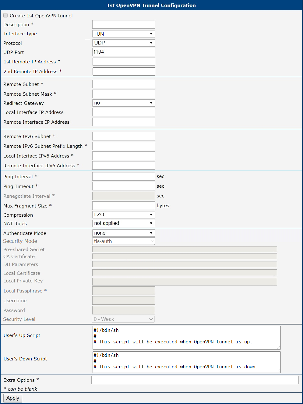
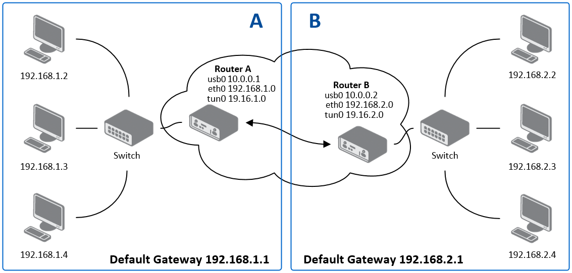
Example
This example shows a basic site-to-site OpenVPN tunnel between Router A and Router B.
| Configuration | Router A | Router B |
|---|---|---|
| Protocol | UDP | UDP |
| UDP Port | 1194 | 1194 |
| Remote IP Address | 10.0.0.2 | 10.0.0.1 |
| Remote Subnet | 192.168.2.0 | 192.168.1.0 |
| Remote Subnet Mask | 255.255.255.0 | 255.255.255.0 |
| Local Interface IP Address | 19.16.1.0 | 19.16.2.0 |
| Remote Interface IP Address | 19.16.2.0 | 19.16.1.0 |
| Compression | none | none |
| Authentication Mode | none | none |
Info
For more detailed examples, including certificate-based authentication, refer to the application note OpenVPN Tunnel.
IPsec
The IPsec tunnel feature enables you to create secure connections between two separate LAN networks. You can configure up to four IPsec tunnels, with support for both IPv4 and IPv6 dual stack operation.
To configure an IPsec tunnel, select IPsec from the Configuration section of the main menu. The menu will expand to show configuration pages for each tunnel (1st Tunnel through 4th Tunnel).
The system supports both policy-based and route-based VPN approaches. You can transport IPv6 traffic through IPv4 tunnels and vice versa using the dual stack capability.
Warning
When configuring IPsec tunnels, keep these key points in mind:
- To encrypt data between local and remote subnets, specify the appropriate values in the subnet fields on both routers. To encrypt only the data stream between the routers, leave the local and remote subnet fields blank.
- If you specify protocol and port information in the Local Protocol/Port field, the router will encapsulate only packets matching those settings.
- For an optimal and secure setup, follow the instructions on the strongSwan Security Recommendations page.
Info
- Detailed information and more examples of IPsec tunnel configuration can be found in the IPsec Tunnel Application Guide.
- The FRR Router App is an Internet routing protocol suite for Advantech routers. It includes protocol daemons for BGP, IS-IS, LDP, OSPF, PIM, and RIP.
Policy-based vs. Route-based VPN
The router supports two VPN modes, selectable via the Type field on the IPsec configuration page. The key differences are summarized in the table below.
| Feature | Policy-based | Route-based |
|---|---|---|
| Traffic selection | Subnet pairs defined in Local Subnet and Remote Subnet fields | Routing table entries |
| Virtual interface | None | ipsecX interface is created |
| Traffic inspection | Not possible on tunnel traffic | Possible using tcpdump -i ipsecX |
| Dynamic routing | Not supported | Supported (e.g., FRR/BGP, FRR/OSPF) |
| Multiple clients | Limited | Fully supported |
| Cisco FlexVPN | Not supported | Supported |
| Configuration complexity | Lower | Higher |
In policy-based mode, the router encrypts traffic based on configured security policies defined by the subnet pairs in Local Subnet and Remote Subnet. No virtual interface is created — the kernel's policy engine handles encapsulation transparently. This is the simpler approach and is suitable for most standard site-to-site VPN deployments.
In route-based mode, a virtual ipsecX interface is created for each tunnel. Traffic is routed into the tunnel using standard routing rules, which enables dynamic routing protocols and more flexible topologies. The available route-based scenarios are described in the Configuration Scenarios section.
Tips
When using policy-based mode, if neither Local Subnet nor Remote Subnet is configured, only router-to-router traffic is encrypted — no LAN-to-LAN traffic will pass through the tunnel.
Configuration Scenarios
The following scenarios describe the most common VPN topologies supported by Advantech routers. The examples use route-based mode, but — with the exception of scenarios 2 and 3 — they are equally applicable to policy-based mode.
Enabled Installing Routes
- Remote and local subnets are used as traffic selectors (routes).
- This results in the same outcome as a policy-based VPN.
- A benefit of this approach is the ability to inspect unencrypted traffic on the
ipsecXinterface using a tool liketcpdump -i ipsecX. - Set Install Routes to yes.
Static Routes (route-based only)
- Routes are installed statically by an application as soon as the IPsec tunnel is established.
- An application like FRR/STATICD can be used for this purpose.
- Set Install Routes to no.
Dynamic Routing (route-based only)
- Routes are installed dynamically by a routing protocol application, such as FRR/BGP or FRR/OSPF.
- Set Install Routes to no.
Multiple Clients
- This allows for a VPN network with multiple clients. One router acts as the server and assigns IP addresses to all clients.
- The server has Remote Virtual Network and Remote Virtual Mask configured, while clients use the Local Virtual Address setting.
- Set Install Routes to yes.
IPsec Authentication Scenarios
The system supports four primary authentication options:
Pre-shared Key
- Set Authenticate Mode to pre-shared key
- Enter the shared key in the Pre-shared Key field
Public Key
- Set Authenticate Mode to X.509 certificate
- Enter the public key in the Local Certificate/PubKey field
- CA certificate not required
Peer Certificate
- Set Authenticate Mode to X.509 certificate
- Enter the remote key in the Remote Certificate/PubKey field
- Allows users with this certificate
- CA certificate not required
CA Certificate
- Set Authenticate Mode to X.509 certificate
- Enter the CA certificate or certificate list in the CA Certificate field
- Accepts any certificate signed by the CA
- Remote certificate not required
Note that Peer and CA Certificate authentication methods can be used simultaneously, allowing authentication through either method. The Local ID is significant - when using certificate authentication, the IKE identity must be contained in the certificate as either subject or subjectAltName.
Configuration Items Description
The configuration GUI for IPsec is shown in the figure below, and the description of all items is provided in the following table.
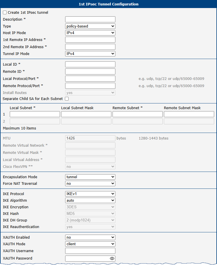
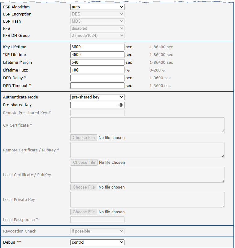
| Item | Description |
|---|---|
| Description | Name or description of the tunnel. |
| Type | • policy-based: Choose for the policy-based VPN approach. • route-based: Choose for the route-based VPN approach. Note: Data throughput via route-based VPN is slightly lower in comparison with policy-based VPN. |
| Host IP Mode | • IPv4: The router communicates via IPv4 with the opposite side of the tunnel. • IPv6: The router communicates via IPv6 with the opposite side of the tunnel. |
| 1st Remote IP Address | First IPv4, IPv6 address or domain name of the remote side of the tunnel, based on selected Host IP Mode above. |
| 2nd Remote IP Address | Secondary (failover) IPv4, IPv6 address or domain name of the remote peer, based on selected Host IP Mode. If configured, at startup the router connects to the 1st Remote IP Address. If that fails, the router attempts the 2nd Remote IP Address. Once established, the router continues using the secondary until it fails — it does not automatically switch back to the primary. |
| Tunnel IP Mode | • IPv4: The IPv4 communication runs inside the tunnel. • IPv6: The IPv6 communication runs inside the tunnel. |
| Remote ID | Identifier (ID) of remote side of the tunnel. It consists of two parts: a hostname and a domain-name. |
| Local ID | Identifier (ID) of local side of the tunnel. It consists of two parts: a hostname and a domain-name. |
| Install Routes | For route-based type only. Choose yes to use traffic selectors as route(s). |
| First Remote Subnet | IPv4 or IPv6 address of a network behind remote side of the tunnel, based on Tunnel IP Mode above. |
| First Remote Subnet Mask/Prefix | IPv4 subnet mask of a network behind remote side of the tunnel, or IPv6 prefix (single number 0 to 128). |
| Second Remote Subnet | IPv4 or IPv6 address of the second network behind remote side of the tunnel, based on Tunnel IP Mode above. For IKE Protocol = IKEv2 only. |
| Second Remote Subnet Mask/Prefix | IPv4 subnet mask of the second network behind remote side of the tunnel, or IPv6 prefix (single number 0 to 128). For IKE Protocol = IKEv2 only. |
| Remote Protocol/Port | Specifies Protocol/Port of remote side of the tunnel. The general form is protocol/port, for example 17/1701 for UDP (protocol 17) and port 1701. It is also possible to enter only the number of protocol, however, the above-mentioned format is preferred. |
| First Local Subnet | IPv4 or IPv6 address of a local network, based on Tunnel IP Mode above. |
| First Local Subnet Mask/Prefix | IPv4 subnet mask of a local network, or IPv6 prefix (single number 0 to 128). |
| Second Local Subnet | IPv4 or IPv6 address of the second local network, based on Tunnel IP Mode above. For IKE Protocol = IKEv2 only. |
| Second Local Subnet Mask/Prefix | IPv4 subnet mask of the second local network, or IPv6 prefix (single number 0 to 128). For IKE Protocol = IKEv2 only. |
| Local Protocol/Port | Specifies Protocol/Port of a local network. The general form is protocol/port, for example 17/1701 for UDP (protocol 17) and port 1701. It is also possible to enter only the number of protocol, however, the above-mentioned format is preferred. |
| MTU | Maximum Transmission Unit value (for route-based mode only). Default value is 1426 bytes. |
| Remote Virtual Network | Specifies virtual remote network for server (responder). |
| Remote Virtual Mask | Specifies virtual remote network mask for server (responder). |
| Local Virtual Address | Specifies virtual local network address for client. To get address from server set up the address to 0.0.0.0. |
| Cisco FlexVPN | Enable to support the Cisco FlexVPN functionality. The route-based type must be chosen. For more information, see strongswan.conf page. |
| Encapsulation Mode | Specifies the IPsec mode, according to the method of encapsulation. • tunnel: entire IP datagram is encapsulated. • transport: only IP header is encapsulated. Not supported by route-based VPN. • beet: the ESP packet is formatted as a transport mode packet, but the semantics of the connection are the same as for tunnel mode. |
| Force NAT Traversal | Enable NAT traversal enforcement (UDP encapsulation of ESP packets). |
| IKE Protocol | Specifies the version of IKE (IKEv1/IKEv2, IKEv1 or IKEv2). |
| IKE Algorithm | Specifies the means by which the router selects the algorithm: • auto: The encryption and hash algorithm are selected automatically. • manual: The encryption and hash algorithm are defined by the user. |
| IKE Encryption | Encryption algorithm: 3DES, AES128, AES192, AES256, AES128GCM128, AES192GCM128, AES256GCM128. |
| IKE Hash | Hash algorithm: MD5, SHA1, SHA256, SHA384 or SHA512. |
| IKE DH Group | Specifies the Diffie-Hellman groups which determine the strength of the key used in the key exchange process. Higher group numbers are more secure, but require more time to compute the key. |
| IKE Reauthentication | Enable or disable IKE reauthentication (for IKEv2 only). |
| XAUTH Enabled | Enable extended authentication (for IKEv1 only). |
| XAUTH Mode | Select XAUTH mode (client or server). |
| XAUTH Username | XAUTH username. |
| XAUTH Password | XAUTH password. |
| ESP Algorithm | Specifies the means by which the router selects the algorithm: • auto: The encryption and hash algorithm are selected automatically. • manual: The encryption and hash algorithm are defined by the user. |
| ESP Encryption | Encryption algorithm: DES, 3DES, AES128, AES192, AES256, AES128GCM128, AES192GCM128, AES256GCM128 , CAMELLIA192, CAMELLIA256, CHACHA20POLY1305. |
| ESP Hash | Hash algorithm: MD5, SHA1, SHA256, SHA384 or SHA512. |
| PFS | Enables/disables the Perfect Forward Secrecy function. The function ensures that derived session keys are not compromised if one of the private keys is compromised in the future. |
| PFS DH Group | Specifies the Diffie-Hellman group number (see IKE DH Group). |
| Key Lifetime | Lifetime key data part of tunnel. The minimum value of this parameter is 60 s. The maximum value is 86400 s. |
| IKE Lifetime | Lifetime key service part of tunnel. The minimum value of this parameter is 60 s. The maximum value is 86400 s. |
| Rekey Margin | Specifies how long before a connection expires that the router attempts to negotiate a replacement. Specify a maximum value that is less than half of IKE and Key Lifetime parameters. |
| Rekey Fuzz | Percentage of time for the Rekey Margin extension. |
| DPD Delay | Time after which the IPsec tunnel functionality is tested. |
| DPD Timeout | The period during which device waits for a response. |
| Authenticate Mode | Specifies the means by which the router authenticates: • Pre-shared key: Sets the shared key for both sides of the tunnel. • X.509 Certificate: Allows X.509 authentication in multiclient mode. |
| (Local) Pre-shared Key | Specifies the shared key (local for IKEv2) for both sides of the tunnel. The prerequisite for entering a key is that you select pre-shared key as the authentication mode. |
| Remote Pre-shared Key | Specifies the remote shared key (for IKEv2) for both sides of the tunnel. The prerequisite for entering a key is that you select pre-shared key as the authentication mode. |
| CA Certificate | Certificate for X.509 authentication. |
| Remote Certificate \ PubKey | Certificate for X.509 authentication or PubKey for public key signature authentication. |
| Local Certificate \ PubKey | Certificate for X.509 authentication or PubKey for public key signature authentication. |
| Local Private Key | Private key for X.509 authentication. |
| Local Passphrase | Passphrase used during private key generation. |
| Revocation Check | Certificate revocation policy: • if possible: Fails only if a certificate is revoked, i.e. it is explicitly known that it is bad. • if URI defined: Fails only if a CRL/OCSP URI is available, but certificate revocation checking fails, i.e. there should be revocation information available, but it could not be obtained. • always: Fails if no revocation information is available, i.e. the certificate is not known to be unrevoked. |
| Debug | Choose the level of logging verbosity from: silent, audit, control (default), control-more, raw, private (most verbose including the private keys). See Logger Configuration in strongSwan web page for more details. |
We recommend that you keep up the default settings. When you set key exchange times higher, the tunnel produces lower operating costs, but the setting also provides less security. Conversely, when you reducing the time, the tunnel produces higher operating costs, but provides for higher security.
Warning
- If local and remote subnets are not configured, only packets between local and remote IP addresses are encapsulated, so only router-to-router communication is encrypted.
- If protocol/port fields are configured, only packets matching those settings are encapsulated.
Basic IPv4 IPsec Tunnel Configuration Example
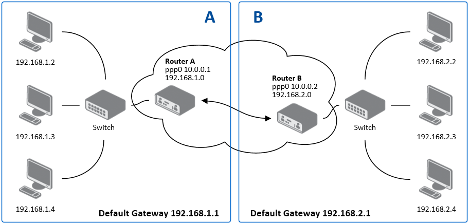
Configuration of Router A and Router B is as follows:
| Configuration | Router A | Router B |
|---|---|---|
| Host IP Mode | IPv4 | IPv4 |
| 1st Remote IP Address | 10.0.0.2 | 10.0.0.1 |
| Tunnel IP Mode | IPv4 | IPv4 |
| First Remote Subnet | 192.168.2.0 | 192.168.1.0 |
| First Remote Subnet Mask | 255.255.255.0 | 255.255.255.0 |
| First Local Subnet | 192.168.1.0 | 192.168.2.0 |
| First Local Subnet Mask | 255.255.255.0 | 255.255.255.0 |
| Authenticate mode | pre-shared key | pre-shared key |
| Pre-shared key | test | test |
TPM-based Authentication
This section describes the process of creating the TPM keys usable for an IPSec tunnel configuration. This feature uses the TPM 2.0 (Trusted Platform Module) chip mounted directly onto the router’s mainboard. For details about the TPM commands, see the tpm2 command description or go to TPM2 Tools Documentation.
To generate the key, connect to the "TPM-equipped" router's console and execute the following commands:
$ tpm2 createek -c ek.ctx -G rsa

$ tpm2 createak -C ek.ctx -G rsa -g sha256 -s rsassa -c ak_rsa.ctx -u ak_rsa.pub -f pem
loaded-key:
  name: 000b0a688495f33b96ecfe242807e5b183a41bc5f24f7a4f18716866d084378a6cd2
  qualified name: 000bffac43e487a8658606636a9640e02151ec0603bec90073dd2bc2e8b82f07ff9a

$ tpm2 evictcontrol -c ak_rsa.ctx
persistent-handle: 0x81010001
action: persisted
After this, store the ak_rsa.pub, which is the public key in a standard PEM format, and remember the persistent-handle such as 0x81010001 that got printed. This is the location (handle) of the private key. The temporary *.ctx files can be removed at this point.
To list all existing handles, execute the following command:
$ tpm2 getcap handles-persistent
- 0x81010001
To configure the key for an IPsec tunnel in the GUI:
- Set Authentication Mode to** X509 Certificate** on both routers.
- Place content of
ak_rsa.pubas local pubkey (item Local Certificate / PubKey) to the router and as a remote pubkey (item Remote Certificate / PubKey) to the peer router. - Put the persistent-handle number printed by
tpm2 evictcontrolcommand above (such as0x81010001) as a private key (item Local Private Key) to the router.
To remove a persisted key, execute the following command:
$ tpm2 evictcontrol -c 0x81010001
persistent-handle: 0x81010001
action: evicted
WireGuard
WireGuard is a modern, secure, and high-performance VPN (Virtual Private Network) protocol and opensource software that creates encrypted tunnels. It is designed for ease of use, speed, and a reduced attack surface compared to older protocols like IPsec and OpenVPN. WireGuard operates by encapsulating traffic within UDP (User Datagram Protocol) packets. Advantech routers support the creation of up to four WireGuard tunnels simultaneously.
To access the WireGuard tunnel configuration pages, click WireGuard in the Configuration section of the main menu. The menu item will expand, displaying separate configuration pages for 1st Tunnel, 2nd Tunnel, 3rd Tunnel, and 4th Tunnel.
WireGuard on Advantech routers supports both IPv4 and IPv6 tunnels (dual stack), enabling the transport of IPv6 traffic over IPv4 tunnels and vice versa.
Info
- The FRRouting (FRR) router app is an Internet routing protocol suite for Advantech routers. This User Module includes protocol daemons for BGP, IS-IS, LDP, OSPF, PIM, and RIP. FRR can be used in conjunction with WireGuard for dynamic routing configurations.
- Detailed information and practical examples of WireGuard tunnel configuration and authentication can be found in the application note WireGuard Tunnel.
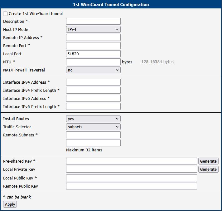
The following table describes all available WireGuard tunnel configuration options:
| Parameter | Description |
|---|---|
| Description | A user-defined name or description for the WireGuard tunnel interface. |
| Host IP Mode | • IPv4: The router uses IPv4 for communication with the remote peer. • IPv6: The router uses IPv6 for communication with the remote peer. |
| Remote IP Address | The IPv4 or IPv6 address, or the domain name, of the remote WireGuard peer. This address must correspond to the selected Host IP Mode. |
| Remote Port | The UDP port number on the remote WireGuard peer where it is listening for incoming connections. |
| Local Port | The UDP port number on which the local WireGuard interface listens for incoming connections (default port is 51820). |
| MTU | The Maximum Transmission Unit (MTU) for the WireGuard tunnel interface, specified in bytes. The default value is 1400 bytes. It’s generally recommended to keep the default value unless specific network conditions require adjustment. |
| NAT/Firewall Traversal | When set to yes, the router sends keepalive packets (every 25 seconds) to maintain the tunnel connection active, especially when the local peer is behind a NAT (Network Address Translation) device or firewall. This ensures the NAT/firewall mapping remains valid, allowing incoming connections to reach the peer behind NAT. |
| Interface IPv4 Address | The IPv4 address assigned to the local WireGuard tunnel interface. This address is used for routing traffic within the tunnel. |
| Interface IPv4 Prefix Length | The IPv4 subnet prefix length associated with the local WireGuard tunnel interface address. |
| Interface IPv6 Address | The IPv6 address assigned to the local WireGuard tunnel interface. This address is used for routing traffic within the tunnel. |
| Interface IPv6 Prefix Length | The IPv6 subnet prefix length associated with the local WireGuard tunnel interface address. |
| Install Routes | • no: Disables automatic route installation. Use this option when a dynamic routing protocol (e.g., FRR/BGP) is used to manage routes. • yes: Enables automatic installation of routes based on the configured subnets. |
| Traffic Selector | • all traffic: All traffic is routed through the WireGuard tunnel (route 0.0.0.0/0 for IPv4 and ::/0 for IPv6). • subnets: Traffic is routed through the WireGuard tunnel based on the specific subnets defined below. |
| Remote Subnets | If Traffic Selector is set to subnets, specify the destination subnets (networks) to be routed through the WireGuard tunnel in CIDR notation (e.g., 192.168.1.0/24). A maximum of 32 subnets can be defined. |
Cryptographic Keys
WireGuard's security is based on modern public-key cryptography.
| Item | Description |
|---|---|
| Local Private Key | The secret private key for this router. Click Generate to create a new one. This key must never be shared. |
| Local Public Key | The public key derived from the local private key. Share this key with the remote peer so it can authenticate and encrypt traffic sent to this router. |
| Remote Public Key | The public key of the remote peer. Used to authenticate the remote peer and encrypt traffic sent to it. |
| Pre-shared Key | An optional key that adds an additional layer of symmetric-key encryption, providing post-quantum resistance. Click Generate to create a new key and share it with the remote peer. |
Example
The following example demonstrates a WireGuard IPv4 tunnel configuration between Router A and Router B.
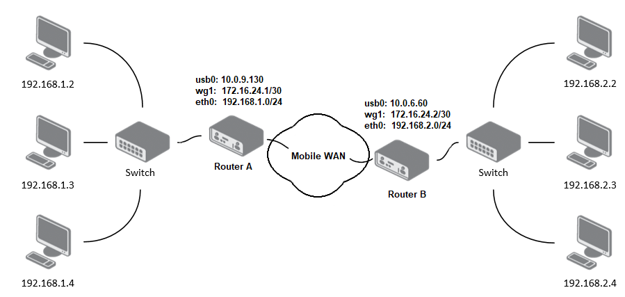
In this setup, Router B is configured as the listening side (server), and Router A initiates the tunnel connection (client). The configuration details for Router A and Router B, based on the topology shown above, are as follows:
| Configuration | Router A | Router B |
|---|---|---|
| Host IP Mode | IPv4 | IPv4 |
| Remote IP Address | 10.0.6.60 | : |
| Remote Port | 51820 | : |
| Local Port | 51820 | 51820 |
| NAT/Firewall Traversal | yes | no |
| Interface IPv4 Address | 172.16.24.1 | 172.16.24.2 |
| Interface IPv4 Prefix Length | 30 | 30 |
| Install Routes | yes | yes |
| Traffic Selector | subnets | subnets |
| Remote Subnets | 192.168.2.0/24 | 192.168.1.0/24 |
| Local Private Key | local private key | local private key |
| Local Public Key | local public key | local public key |
| Remote Public Key | public key of the opposite side | public key of the opposite side |
Verifying Connectivity
After applying the configuration, verify the tunnel status on the Status → WireGuard page. A successful connection is indicated by the presence of a Latest handshake time, which shows how long ago the last cryptographic key exchange occurred. This value will only appear after traffic has been initiated from the client side (Router A) or after the first keepalive packet has been sent.
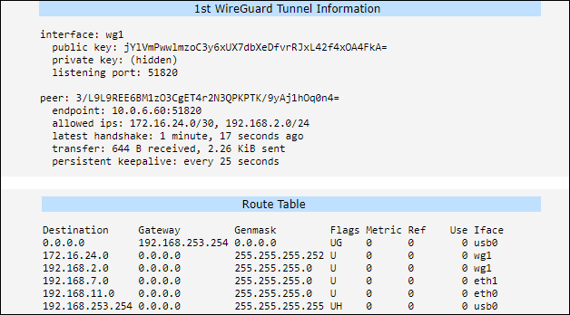
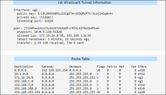
VXLAN
Info
VXLAN does not provide any native encryption or authentication. When deploying VXLAN over public or untrusted networks, it is strongly recommended to route the VXLAN traffic through a secure VPN tunnel, such as IPsec or WireGuard, to ensure data confidentiality and integrity.
Virtual Extensible LAN (VXLAN) is a Layer 2 overlay scheme on a Layer 3 network. It uses a VLAN-like encapsulation to wrap Layer 2 Ethernet frames within Layer 3 UDP packets. This allows for the creation of virtualized Layer 2 subnets that can span across physical Layer 3 network boundaries. Advantech routers support up to four simultaneous VXLAN tunnels. The configuration pages for VXLAN are located under Configuration → VXLAN.
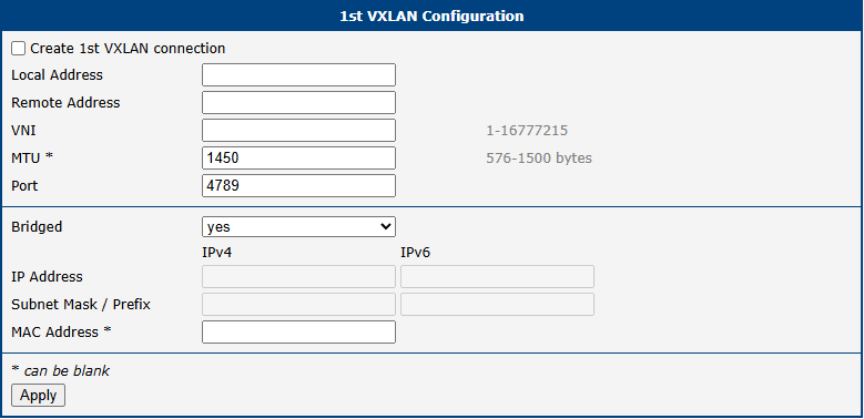
The table below describes the parameters available for configuring each of the VXLAN interfaces.
| Item | Description |
|---|---|
| Create VXLAN connection | Activates the selected VXLAN tunnel (1st to 4th). |
| Local Address | The local IP address of the router used as the source for the VXLAN tunnel. |
| Remote Address | The IP address of the remote tunnel peer (VTEP). For secure deployments, this should be the internal IP of an established VPN tunnel. |
| VNI | VXLAN Network Identifier (1 to 16777215). This ID must be identical on both VTEP peers. |
| MTU | Maximum Transmission Unit (576 to 1500 bytes). The recommended value is 1450 to account for the 50-byte VXLAN overhead and prevent fragmentation. This field can be left blank. |
| Port | The destination UDP port used for the outer header. The standard port is 4789. |
| Bridged | Select yes to add the VXLAN interface to the router's local bridge, enabling seamless Layer 2 connectivity. If set to no, the VXLAN interface is considered "Routed" and has its own IP address. |
| IP Address | The IPv4 or IPv6 address assigned to the VXLAN interface. Configured when Bridged is set to no (Routed mode). |
| Subnet Mask / Prefix | The corresponding IPv4 subnet mask or IPv6 prefix length for the assigned IP address. |
| MAC Address | A custom MAC address for the VXLAN interface. If specified, the address must be unicast and locally administered. This field is optional and can be left blank. |
VXLAN configuration parameters
Deployment Example
In this scenario, two routers bridge their local networks over an existing WireGuard tunnel to ensure security. The Bridged option is enabled to allow Layer 2 traffic (such as broadcast or non-IP protocols) to pass transparently through the secure tunnel.
| Setting | Router A (Site 1) | Router B (Site 2) |
|---|---|---|
| Local Address | 10.0.0.1 (VPN IP) | 10.0.0.2 (VPN IP) |
| Remote Address | 10.0.0.2 (VPN IP) | 10.0.0.1 (VPN IP) |
| VNI | 100 | 100 |
| Port | 4789 | 4789 |
| Bridged | yes | yes |
Example of secure VXLAN bridge over VPN
Security Recommendations
To protect your network when using VXLAN, follow these best practices:
- Use VPN Transport: Never expose unencrypted VXLAN traffic directly to the internet. Always encapsulate it within IPsec or WireGuard.
- Firewall Whitelisting: Configure the firewall under Configuration → Firewall to allow incoming traffic on UDP port
4789only from the trusted peer IP address. - MTU Adjustment: Ensure the MTU is correctly set (e.g.,
1450) to avoid packet fragmentation issues caused by the combination of VPN and VXLAN headers.
GRE Tunnel
Generic Routing Encapsulation (GRE) is a tunneling protocol that encapsulates a wide variety of network layer protocols inside virtual point-to-point links over an IP network. The router supports creating up to four GRE tunnels.
The configuration pages are located under Configuration → GRE, with separate tabs for each tunnel.
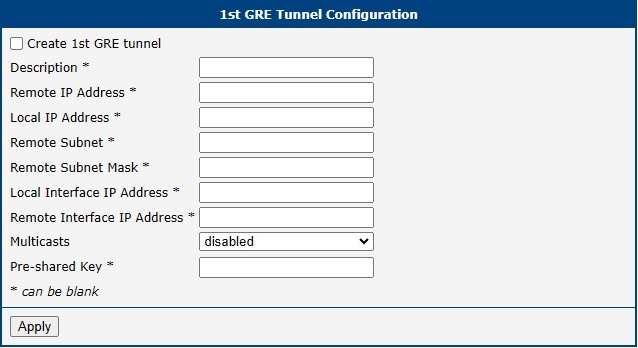
Warning
- GRE is an unencrypted protocol and does not support IPv6 transport. For secure communication, use it in combination with IPsec.
- GRE tunnels cannot pass through a NAT device without a corresponding NAT traversal solution, such as a port forwarding rule for protocol 47 (GRE).
Tunnel Configuration
The following table describes the parameters for configuring a GRE tunnel.
| Item | Description |
|---|---|
| Description | An optional name or description for the tunnel. |
| Remote IP Address | The public IP address of the remote tunnel endpoint. |
| Local IP Address | The public IP address of the local tunnel endpoint. |
| Remote Subnet | The IP address of the destination network behind the remote endpoint. |
| Remote Subnet Mask | The subnet mask of the remote network. |
| Local Interface IP Address | The virtual IP address of the local end of the GRE tunnel interface. |
| Remote Interface IP Address | The virtual IP address of the remote end of the GRE tunnel interface. |
| Multicasts | Controls multicast traffic through the tunnel: • disabled: Blocks multicast traffic. • enabled: Allows multicast traffic. |
| Pre-shared Key | An optional 32-bit numerical key for basic packet validation. Both routers must use the same key, or packets will be dropped. This is not a cryptographic key and provides no security. |
Configuration Example
This example shows a basic site-to-site GRE tunnel between Router A and Router B, connecting their respective LANs.
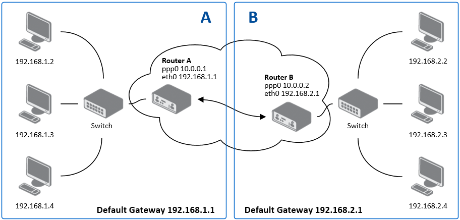
| Configuration | Router A | Router B |
|---|---|---|
| Remote IP Address | 10.0.0.2 | 10.0.0.1 |
| Remote Subnet | 192.168.2.0 | 192.168.1.0 |
| Remote Subnet Mask | 255.255.255.0 | 255.255.255.0 |
Info
For more detailed examples, refer to the application note GRE Tunnel.
L2TP Tunnel
Layer 2 Tunneling Protocol (L2TP) is a tunneling protocol used to support virtual private networks (VPNs) or as part of the delivery of services by ISPs. It does not provide any encryption itself; it relies on an encryption protocol that it passes within the tunnel to provide privacy.
The L2TP configuration page is located under Configuration → L2TP.
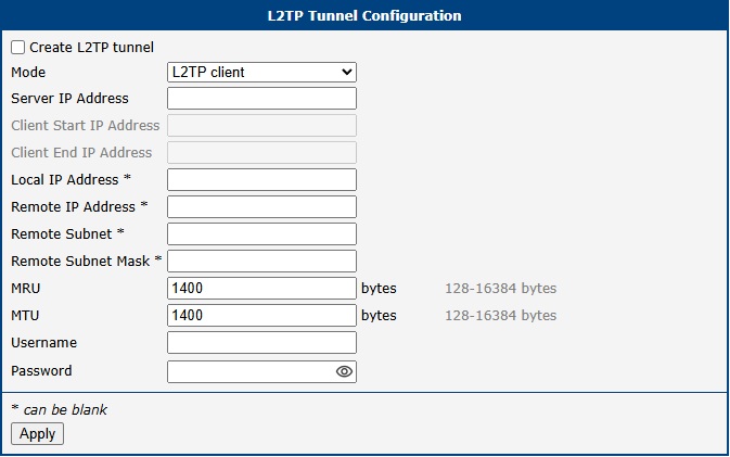
Warning
L2TP is an unencrypted protocol and does not support IPv6 transport. For secure communication, it must be combined with a security protocol like IPsec.
Tunnel Configuration
To set up an L2TP tunnel, check the Create L2TP tunnel box and configure the following parameters.
| Item | Description |
|---|---|
| Mode | Determines the router's role in the L2TP connection: • L2TP server: The router acts as the L2TP Network Server (LNS), accepting connections from clients. • L2TP client: The router acts as the L2TP Access Concentrator (LAC), initiating a connection to a remote server. |
| Server IP Address | (Client mode only) The IP address of the remote L2TP server. |
| Client Start/End IP Address | (Server mode only) The starting and ending addresses of the IP pool from which the server assigns addresses to connecting clients. |
| Local IP Address | The virtual IP address of the local end of the L2TP tunnel. |
| Remote IP Address | The virtual IP address of the remote end of the L2TP tunnel. |
| Remote Subnet/Mask | The IP address and subnet mask of the network behind the remote peer, used for creating a static route. |
| MRU/MTU | The Maximum Receive Unit and Maximum Transmission Unit in bytes. The default value is 1400. |
| Username/Password | The credentials used for authenticating the L2TP session. Valid characters only — refer to Allowed and Restricted Input Characters. |
Configuration Example
This example shows a typical client-server setup, where Router A (Server) provides access to its LAN for Router B (Client).
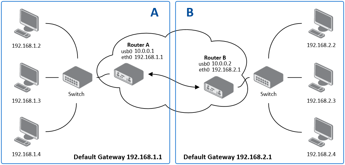
| Configuration | Router A (Server) | Router B (Client) |
|---|---|---|
| Mode | L2TP Server | L2TP Client |
| Server IP Address | : | 10.0.0.1 |
| Client Start IP Address | 192.168.2.5 | : |
| Client End IP Address | 192.168.2.254 | : |
| Local IP Address | 192.168.1.1 | : |
| Remote Subnet | 192.168.2.0 | 192.168.1.0 |
| Remote Subnet Mask | 255.255.255.0 | 255.255.255.0 |
| Username | username | username |
| Password | password | password |
PPTP Tunnel
Point-to-Point Tunneling Protocol (PPTP) is a tunneling protocol used to create simple, password-protected connections between two LANs. To configure a tunnel, navigate to Configuration → PPTP.
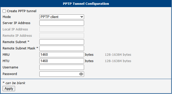
Warning
PPTP is an outdated and insecure protocol with known vulnerabilities. It does not support IPv6. It is strongly recommended to use a modern, secure VPN protocol such as WireGuard or OpenVPN instead.
Tunnel Configuration
To set up a PPTP tunnel, check the Create PPTP tunnel box and configure the following parameters.
| Item | Description |
|---|---|
| Mode | Determines the router's role in the PPTP connection: • PPTP server: The router acts as the server, accepting connections from remote clients. • PPTP client: The router acts as the client, initiating a connection to a remote server. |
| Server IP Address | (Client mode only) The IP address of the remote PPTP server. |
| Local IP Address | The virtual IP address for the local end of the tunnel. |
| Remote IP Address | The virtual IP address for the remote end of the tunnel. |
| Remote Subnet/Mask | The IP address and subnet mask of the network behind the remote peer. |
| MRU/MTU | The Maximum Receive Unit and Maximum Transmission Unit in bytes. The default value is 1460 to avoid packet fragmentation. |
| Username/Password | The credentials for authenticating the PPTP session. Valid characters only — refer to Allowed and Restricted Input Characters. |
Info
The router firmware also supports PPTP passthrough, which allows PPTP client devices on the LAN to establish tunnels through the router to an external server.
Configuration Example
This example shows a standard client-server setup where Router A (Server) accepts a connection from Router B (Client).
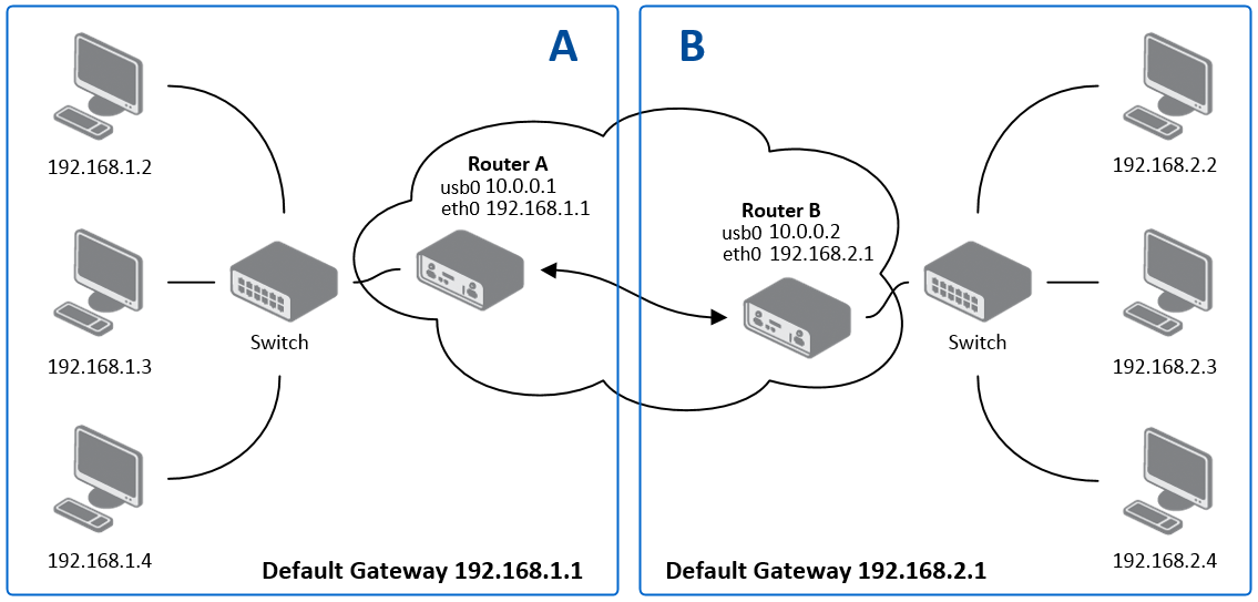
| Configuration | Router A (Server) | Router B (Client) |
|---|---|---|
| Mode | PPTP Server | PPTP Client |
| Server IP Address | : | 10.0.0.1 |
| Local IP Address | 192.168.1.1 | : |
| Remote IP Address | 192.168.2.1 | : |
| Remote Subnet | 192.168.2.0 | 192.168.1.0 |
| Remote Subnet Mask | 255.255.255.0 | 255.255.255.0 |
| Username | username | username |
| Password | password | password |
Services
The following sections describe the configuration of services that can be accessed by expanding the menu Configuration → Services.
Authentication
User authentication options are configured on the Configuration → Authentication page. The basic configuration interface shows settings for the local user database mode. Common configuration options apply across all authentication modes.
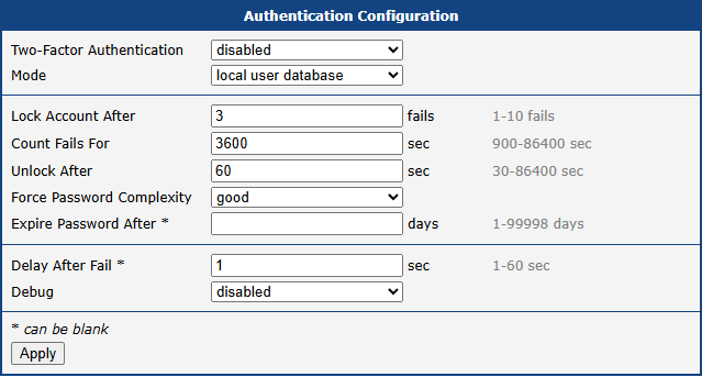
| Parameter | Description |
|---|---|
| Two-Factor Authentication | Enable two-factor authentication using either Google Authenticator or OATH Toolkit, refer to Two-Factor Authentication. |
| Mode | • Local user database: Authenticate against local database only, refer to Manage Users. • RADIUS with fallback: Try RADIUS first, then local database if RADIUS is unavailable. • RADIUS only: Use RADIUS exclusively. Warning: No authentication possible if RADIUS server is unreachable. • TACACS+ with fallback: Try TACACS+ first, then local database if TACACS+ is unavailable. • TACACS+ only: Use TACACS+ exclusively. Warning: No authentication possible if TACACS+ server is unreachable. |
| Lock Account After | Number of failed login attempts before account lockout. |
| Count Fails For | Time window during which failed login attempts are counted. |
| Unlock After | Duration after which a locked account becomes unlocked. |
| Force Password Complexity | Password complexity requirements:
• good: 12 characters using uppercase, lowercase, and numbers (max 3 identical characters in sequence) [FirstNet compliant] Time to crack: Months to years
• strong: 16 characters using uppercase, lowercase, numbers, and special characters Time to crack: Centuries |
| Expire Password After | Days until password expiration and required change, refer to Forced Password Change. |
| Delay After Fail | Wait time before allowing another login attempt after failure. |
| Debug | Enable/disable authentication debugging in Syslog. |
RADIUS Authentication
Warning
When using RADIUS authentication, users must exist in the local database. Users can be created manually or automatically via the "Take Over Server Users" option.
To configure RADIUS authentication, select either RADIUS with fallback or RADIUS only mode and configure the following options:
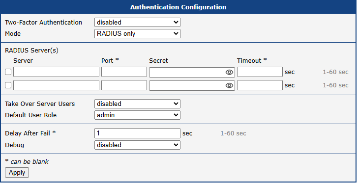
| Parameter | Description |
|---|---|
| Server | RADIUS server address (up to two servers supported). |
| Port | RADIUS server port. |
| Secret | Authentication secret for RADIUS server. |
| Timeout | RADIUS authentication timeout. |
| Take Over Server Users | If enabled, a new user account is created during the login, in case the RADIUS authentication is successful and appropriate local account does not exist. New accounts are created without the password. An existing user account with a password is never modified by this feature. |
| Default User Role | Choose the user role (Admin or User). This role corresponds with router’s user roles, see Manage Users. Selected role will be used for a user in case the option Take Over Server Users is enabled and if the user’s Service-Type set on the RADIUS server is missing or is not set up to NAS-Prompt-User or Administrative-User. When Service-Type is set to NAS-Prompt-User, the User role will be used. When Service-Type is set to Administrative-User, the Admin role is used. |
TACACS+ Authentication
Warning
When using TACACS+ authentication, users must exist in the local database. Users can be created manually or automatically via the "Take Over Server Users" option.
To configure TACACS+ authentication, select either TACACS+ with fallback or TACACS+ only mode and configure the following options:
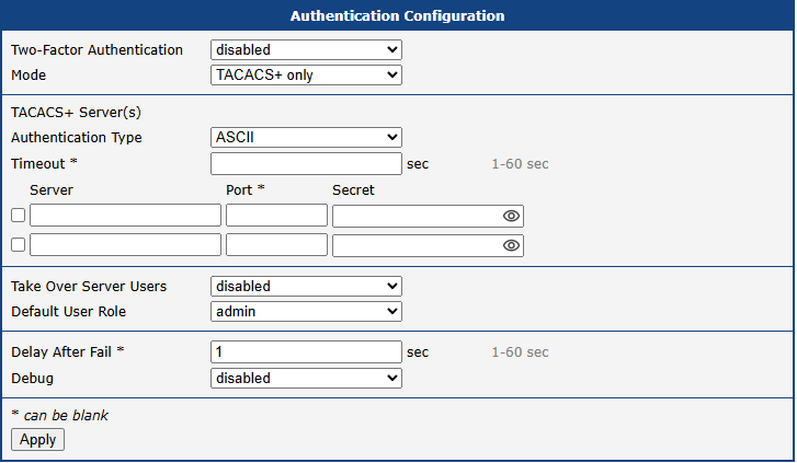
| Parameter | Description |
|---|---|
| Authentication Type | Choose ASCII, PAP, or CHAP authentication type. To configure the two-factor authentication for a user, see Two-Factor Authentication. |
| Timeout | TACACS+ authentication timeout. |
| Server | TACACS+ server address (up to two servers supported). |
| Port | TACACS+ server port |
| Secret | Authentication secret for TACACS+ server |
| Take Over Server Users | If enabled, a new user account is created during the login, in case the TACACS+ authentication is successful and appropriate local account does not exist. New accounts are created without the password. An existing user account with a password is never modified by this feature. |
| Default User Role | Choose the user role (Admin or User). This role corresponds with router’s user roles, see Manage Users. Selected role will be used for a new user when Take Over Server Users is used. |
DynDNS
The Dynamic DNS client allows you to access the router using a fixed, memorable hostname, even if the router’s IP address changes. The client monitors the router’s public IP address and automatically updates the DNS record on a Dynamic DNS server whenever a change is detected. The service supports both standard DDNS (RFC 2136) and secure updates via HTTPS. To configure the service, navigate to Services → Dynamic DNS.
Warning
For the Dynamic DNS service to function correctly, the router’s SIM card must be assigned a public IP address by the mobile provider.
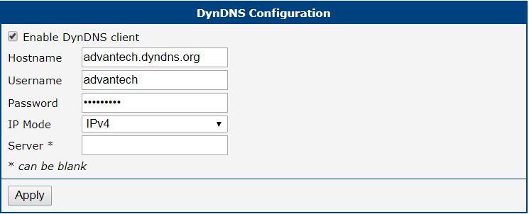
| Item | Description |
|---|---|
| Hostname | Your fully qualified domain name registered with a Dynamic DNS provider (e.g., myrouter.example.com). |
| IP Mode | The IP protocol version for DNS updates: IPv4 (default), IPv6, or IPv4/IPv6 (dual-stack). |
| Service | The protocol for the DNS update: DynDNS (HTTP API) for standard web-based providers, or DDNS (RFC 2136) for direct updates to standard DNS servers. |
| Server | The update server address of your Dynamic DNS provider. If left blank, the default value members.dyndns.org is used. Several free services are available: freedns.afraid.org, www.duckdns.org, www.noip.com. Secure HTTPS URLs are supported. Active only when Service is set to DynDNS (HTTP API). |
| Username | The username for your Dynamic DNS service account. Active only when Service is set to DynDNS (HTTP API). |
| Password | The password for your Dynamic DNS service account. Active only when Service is set to DynDNS (HTTP API). |
| Skip Certificate Verification | Check to bypass SSL/TLS certificate validation when connecting to an HTTPS server. Active only when Service is set to DynDNS (HTTP API). |
| CA Certificate | The Certificate Authority (CA) certificate used to verify the server’s identity during HTTPS updates. Active only when Service is set to DynDNS (HTTP API). |
| TTL | Time to Live for the DNS record, specifying how long the record is cached by DNS resolvers. Default: 60 seconds; range: 5–86400 seconds. Active only when Service is set to DDNS (RFC 2136). |
| TSIG Key | The Transaction Signature key used to authenticate DDNS updates. Active only when Service is set to DDNS (RFC 2136). |
Configuration Example
The example below shows how to configure the router to securely update a dual-stack DNS record using a custom provider’s HTTPS API, with certificate verification enforced.
| Setting | Value |
|---|---|
| Hostname | router.example.com |
| IP Mode | IPv4/IPv6 |
| Service | DynDNS (HTTP API) |
| Server | https://ddns.example.com |
| Username | admin_user |
| Password | <your_secure_password> |
| Skip Certificate Verification | unchecked |
| CA Certificate | <pasted PEM certificate content> |
Info
To access the router’s web interface from the internet, you must also enable Remote Access. For details, see NAT.
FTP
The FTP protocol (File Transfer Protocol) can be used to transfer files between the router and another device on the network. The FTP server is configured on the FTP page under Services.
Warning
FTP is an unencrypted protocol. All data, including credentials, is transmitted in plain text. For secure file transfers, use SFTP over SSH instead.
| Item | Description |
|---|---|
| Enable FTP service | Enabling of FTP server. |
| Maximum Sessions | Indicates how many concurrent connections the FTP server shall accept. Once the maximum is reached, additional connections will be rejected until some of the existing connections are terminated. The range is from 1 to 500. |
| Session Timeout | Is used to close inactive sessions. The server will terminate a FTP session after it has not been used for the given amount of seconds. The range is from 60 to 7200. |
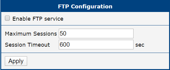
GNSS
Info
- Available only for models equipped with a GNSS module.
- Antenna Placement: GNSS antennas require a direct line of sight to the satellites. Signal reception is generally not possible inside buildings or tunnels without specialized signal repeaters.
- Active vs. Passive Antennas: Active GNSS antennas require power to operate. If an active antenna is connected to a product that supports only passive antennas, no signal will be received.
- Starting from firmware version 6.6.0, this functionality replaces the GPS Router App. It is strongly recommended to use the built-in feature instead of the legacy Router App. Furthermore, it is not possible to use this functionality together with Router App versions earlier than 2.0.0.
The GNSS (Global Navigation Satellite System) page allows you to configure the router's satellite positioning features. When the GNSS service is enabled, the router activates its receiver to acquire satellite signals. This provides several key functionalities:
- Real-time location data becomes available on the router's status pages (see Geolocation and GNSS).
- The router can use GNSS as a source for time synchronization (see NTP).
- If configured, the router's location can be reported via SNMP for network management and monitoring (see SNMP).
This service is essential for applications requiring precise time and location information, such as vehicle tracking, asset management, or synchronizing distributed network devices. The configuration also allows forwarding of raw NMEA data to both local serial ports and remote servers over the network.
| Item | Description |
|---|---|
| Enable GNSS service | Enables or disables the GNSS functionality in the router. When enabled, the router starts acquiring GNSS data from the integrated receiver. |
| Forward NMEA to Local | Select the local interface(s) to which the NMEA output from the GNSS receiver will be forwarded. Available options: • RS-232 port • RS-485 port • serial converter in USB port • pseudoterminal The forwarded data uses fixed settings: 115200 baud, 8 data bits, no parity, 1 stop bit. |
| Forward NMEA to Remote | Configure up to ten remote destinations, each defined by: • Address — Destination IP address or hostname • Protocol — TCP or UDP transport • Port — Destination port • Moving Period — Interval (in seconds) to send data when movement is detected • Halted Period — Interval (in seconds) to send data when the device is stationary Allowed interval is 0–864000 seconds. Ports default to 10110 (NMEA over TCP/UDP). |
| Forward NMEA Sentences | Select which specific NMEA sentence types to forward (RMC, GGA, GNS, VTG, GSA, GSV). This allows filtering of the GNSS data sent to local or remote destinations. |
| Send Router Identification | A custom identification text (1–70 characters) sent to the remote destination as an additional NMEA sentence in the format $GPFID,X. Leave the field blank to omit the ID. |
| Restart when NMEA is unavailable | If enabled, the GNSS service is automatically reset if no data is received for the duration specified in the Unavailability Timeout field. |
| Unavailability Timeout | Defines the maximum time without GNSS data (5–14,400 minutes) before the service is automatically reset. |
GNSS configuration items
Info
Local forwarding is possible simultaneously to multiple hardware ports and one pseudoterminal. NMEA forwarding to remote supports both TCP and UDP and can be configured independently for up to ten remote servers.
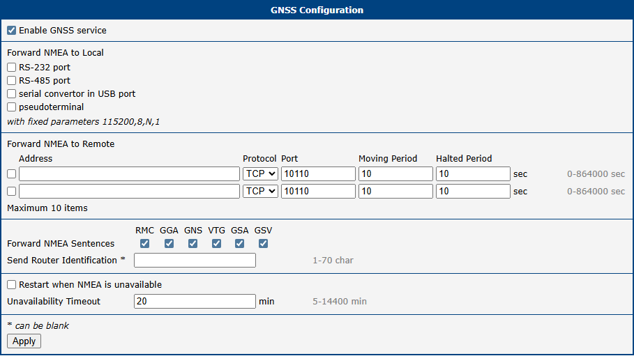
HTTP
Warning
Make sure your certificate matches the Security Level. Increasing Security Level without generating a new certificate may lead to inability to connect to Web GUI.
This page manages access to the router's web configuration interface via HTTP and HTTPS. For maximum security, use HTTPS — it encrypts all communication between the browser and the router. Even if HTTP is disabled, the router continues to listen on port 80 for the sole purpose of redirecting requests to HTTPS.
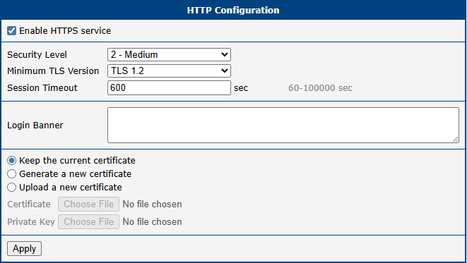
| Item | Description |
|---|---|
| Enable HTTPS service | Enables secure, encrypted access to the web interface. |
| Security Level | Sets the minimum cryptographic strength by controlling which TLS versions and cipher suites are permitted. Options: 2 - Medium (112-bit security), 3 - High (128-bit, requires AES-128 or stronger), 4 - Very High (192-bit, requires AES-192 or stronger). |
| Minimum TLS Version | The minimum TLS version the router's web server will accept. Options: TLS 1.2 and TLS 1.3. |
| Session Timeout | The inactivity period (in minutes) after which a user is automatically logged out. |
| Login Banner | Custom text displayed on the login page above the credentials fields. |
| Keep the current certificate | Retains the certificate currently stored on the router. |
| Generate a new certificate | Generates a new self-signed certificate corresponding to the selected Security Level. |
| Upload a new certificate | Allows uploading a custom certificate, such as one signed by a trusted Certificate Authority. |
| Certificate | The PEM-formatted certificate file to upload. The file may contain a single certificate or a full certificate chain. |
| Private Key | The private key file corresponding to the certificate being uploaded. |
LLDP
Info
Information about discovered neighbors can be viewed on the Status → Network page, under the LLDP Neighbors section.
The Link Layer Discovery Protocol (LLDP) is a vendor-neutral, Layer 2 network protocol used by devices to advertise their identity, capabilities, and neighbors on a local area network. Enabling LLDP on the router facilitates easier network mapping, topology discovery, and troubleshooting in multi-vendor environments. To configure this feature, navigate to Configuration → Services → LLDP.
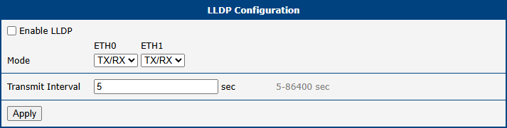
| Item | Description |
|---|---|
| Enable LLDP | Activates the Link Layer Discovery Protocol globally on the router. |
| Mode | Defines the communication mode for all available Ethernet interfaces. For devices equipped with a switch, this includes individual switch ports. Available options per interface: • TX/RX — The port both transmits LLDP advertisements and receives LLDP packets from neighboring devices. • RX — The port only receives LLDP packets. • off — LLDP communication is disabled on this port. |
| Transmit Interval | Specifies the frequency, in seconds, at which LLDP advertisement packets are broadcast to neighbors. The default is 5 seconds; the permitted range is 5 to 86400 seconds. |
LLDP configuration parameters
NTP
The NTP (Network Time Protocol) configuration page allows you to configure the router’s NTP client functionality. To open the NTP configuration page, click NTP in the Configuration section of the main menu.
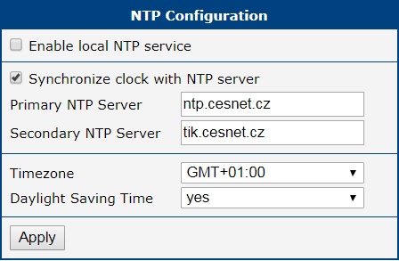
| Item | Description |
|---|---|
| Primary NTP Server Address | IP address or domain name of the primary remote NTP server. This server is queried first for time synchronization. |
| Secondary NTP Server Address | IP address or domain name of the secondary remote NTP server. This server is used if the primary server is unavailable. |
| Timezone | Specifies the geographical timezone where the router is physically located. This setting is crucial for correct local time display and DST adjustments. |
| Daylight Saving Time | Enables or disables automatic adjustment for Daylight Saving Time (DST). When enabled, the router will adjust its clock according to the DST rules for the selected Timezone. |
SNMP
The SNMP page allows you to configure the SNMP v1/v2 or v3 agent, which transmits information about the router and its expansion ports (if applicable) to a management station. To access the page, click SNMP in the Configuration → Services section.
SNMP (Simple Network Management Protocol) provides status information about network elements such as routers or endpoint devices. In SNMP v3, communication is secured through user-specific encryption and authentication. To enable the SNMP service, select the Enable SNMP agent checkbox. IPv6 is supported for SNMP traps as well.
Info
Name, Location, Contact, and Custom identification fields are now configured in Configuration → System → Identification. These fields are no longer present on the SNMP configuration page.
| Item | Description |
|---|---|
| Enable SNMP agent | Turns on the SNMP agent, allowing the router to be managed and monitored using SNMP protocols. |
| Enable SNMPv1/v2 access | Enables access for SNMPv1 and SNMPv2 protocols. Enter community strings for read and write access. |
| Community (Read/Write) | Community strings for SNMPv1/v2 access. Default: public for read, private for write. |
| Enable SNMPv3 access | Activates configuration options for SNMPv3, providing stronger authentication and encryption. |
| Username | The username for SNMPv3, configured independently for read and write access. |
| Authentication | The authentication algorithm (e.g., SHA-512) for SNMPv3 identity verification. |
| Authentication Password | Password for generating the authentication key. Enter valid characters only, refer to Allowed and Restricted Input Characters. |
| Privacy | The encryption algorithm (e.g., AES) used to secure SNMPv3 communication. |
| Privacy Password | Password for encrypting SNMPv3 messages. Enter valid characters only, refer to Allowed and Restricted Input Characters. |
| Enable I/O extension | Allows monitoring and reporting of digital I/O signals available on the router. |
| Enable M-BUS extension | Enables support for M-BUS (Meter-Bus) devices. Configure the baudrate, parity, and stop bits as required for your metering hardware. External RS232/M-BUS converters may be needed. |
| Baudrate, Parity, Stop Bits | Communication parameters for the M-BUS interface. |
| Enable reporting to supervisory system | Enables transmission of statistical and location data to a supervisory or monitoring server. |
| Address | Destination IP address or hostname of the supervisory system. |
| Period | Reporting interval in minutes (1–1440). |
| Location period if moving / halted | Available on GNSS models only. Defines the reporting interval in seconds (0–864000) for location data. Separate values can be configured for when the router is moving and when it is stationary. |
Each monitored value is uniquely identified by a numerical OID (Object Identifier) — a dot-separated sequence of numbers forming a hierarchical tree. The figure below shows the basic tree structure used for creating OIDs.
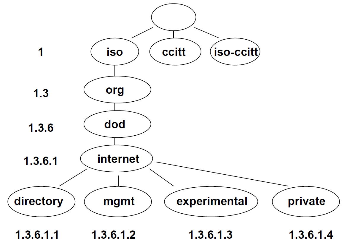
The SNMP values specific to Advantech routers start at OID .1.3.6.1.4.1.30140, interpreted as: iso.org.dod.internet.private.enterprises.conel
The router provides information such as internal temperature (OID 1.3.6.1.4.1.30140.3.3) and power voltage (OID 1.3.6.1.4.1.30140.3.4). For digital inputs and outputs, the following OIDs are used:
| OID | Description |
|---|---|
| .1.3.6.1.4.1.30140.2.3.1.0 | Digital input BIN0 (values: 0, 1) |
| .1.3.6.1.4.1.30140.2.3.2.0 | Digital output OUT0 (values: 0, 1) |
| .1.3.6.1.4.1.30140.2.3.3.0 | Digital input BIN1 (values: 0, 1) |
Info
The list of available and supported OIDs and other details can be found in the application note SNMP Object Identifiers.
SNMP Configuration Example
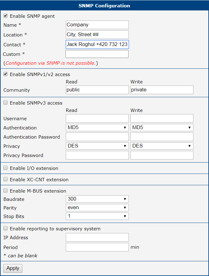
MIB Browser Example
To access a device, enter the router's IP address in the Remote SNMP Agent field. The MIB browser then displays the internal variables in the tree structure. You can also check individual variables by entering their OID.
The path to SNMP objects is: iso → org → dod → internet → private → enterprises → Conel → protocols
The path to router-specific information is: iso → org → dod → internet → mgmt → mib-2 → system
SMTP
The router includes a Simple Mail Transfer Protocol (SMTP) client, which can be configured to send emails for notifications or from scripts. To configure the client, navigate to Services → SMTP.
Info
- The settings on this page must match the requirements of your email provider's SMTP server.
- Some mobile service providers may block standard SMTP ports, potentially restricting you to using the provider's own SMTP server.
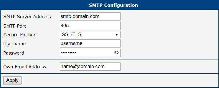
| Item | Description |
|---|---|
| SMTP Server Address | The IP address or domain name of your outgoing mail server. |
| SMTP Port | The port number the SMTP server uses. Common ports: 25, 465 (SSL/TLS), and 587 (STARTTLS). |
| Secure Method | The encryption method required by the server: none, SSL/TLS, or STARTTLS. |
| Username | The username for your email account. |
| Password | The password for your email account. Enter valid characters only, refer to Allowed and Restricted Input Characters. |
| Own Email Address | The sender's email address that will appear on outgoing emails (e.g., my-router@mydomain.com). |
Sending Emails
Once the SMTP client is configured, you can send emails in two ways:
- From a script: Use the
emailcommand within a startup or custom script. Scripts are managed on the Configuration → Scripts page. - From the command line: Connect to the router via SSH and use the
emailcommand directly.
For detailed syntax and examples of the email command, refer to the Command Line Interface for S1 Application Note.
SMS
Open the SMS page in the Services submenu of the Configuration section of the main menu. The router can automatically send SMS messages to a cell phone or SMS message server when certain events occur. The format allows you to select which events generate an SMS message.
| Item | Description |
|---|---|
| Send SMS on power up | Activates/deactivates the sending of an SMS message automatically on power up. |
| Send SMS on connect to mobile network | Activates/deactivates the sending of an SMS message automatically when the router is connected to a mobile network. |
| Send SMS on disconnect to mobile network | Activates/deactivates the sending of an SMS message automatically when the router is disconnection from a mobile network. |
| Send SMS when datalimit exceeded | Activates/deactivates the sending of an SMS message automatically when the data limit exceeded. |
| Send SMS when digital input turns On/Off | Activates/deactivates the sending of an SMS message when a digital input changes state. |
| Add timestamp to SMS | Activates/deactivates the adding a time stamp to the SMS messages. This time stamp has a fixed format YYYY-MM-DD hh:mm:ss. |
| Recipient Number(s) | Specifies the phone number(s) to which the router sends the generated SMS. Multiple numbers can be entered separated by commas. |
| Unit ID | The name of the router. The router sends the name in the SMS. |
| Digital Input 0/1 SMS | Text of the SMS message when a digital input is activated. |
Remote Control via SMS
The router can be controlled by sending specific commands via SMS from an authorized phone number. To activate this functionality, enable it and specify at least one authorized number.
| Item | Description |
|---|---|
| Enable remote control via SMS | Master switch for SMS processing. When disabled, all incoming SMS messages are ignored and neither control commands nor the custom script at /var/scripts/sms will be executed. |
| Authorized Number(s) | A comma-separated list of phone numbers authorized to send control commands. Enter * to accept commands from any phone number. |
Info
- If one or more phone numbers are specified, only those numbers can control the router via SMS.
- Entering
*allows control from any phone number.
Most of the control SMS messages do not change the router configuration. For example, if the router is changed to the off line mode using an SMS message, the router remains in this mode, but it will return back to the on-line mode after reboot. The only exception is set profile command that changes the configuration permanently, see the table below.
To control the router using an SMS, send only message text containing the control command. You can send control SMS messages in the following format:
SMS | Description |
|---|---|
| go online sim [1|2] | Switches the active mobile connection to the specified SIM card. |
| go online | Switch the router to the online mode. |
| go offline | Switch the router to the offline mode. |
| set outx=0 | Set digital output x to 0. Example: set out0=0. |
| set outx=1 | Set digital output x to 1. Example: set out0=1. |
| set profile std | Set the standard profile. This change is permanent. |
| set profile alt1 | Set alternative profile 1. This change is permanent. |
| set profile alt2 | Set alternative profile 2. This change is permanent. |
| set profile alt3 | Set alternative profile 3. This change is permanent. |
| reboot | Reboot the router. |
| get ip | Responds with the current IPv4 address of the active mobile connection. |
| get ipv6 | Responds with the current IPv6 address of the active mobile connection. |
Warning
Note: Every received control SMS is processed and then deleted from the router! This may cause a confusion when you want to use AT-SMS protocol for reading received SMS (see section below).
Info
For advanced users, custom SMS processing can be implemented using a script at /var/scripts/sms. This script is invoked only for messages that are NOT processed as standard control commands (e.g., messages with unknown text or from unauthorized numbers). The Enable remote control via SMS option must be enabled for the script to run. For more details, see the Extending Router Functionality Application Note, chapter Handling Incoming SMS with a Custom Script.
AT-SMS Protocol
Info
The AT-SMS protocol provides direct access to the router's cellular module using standard AT commands. This allows advanced management of SMS messages and retrieval of detailed module status information over a serial port or TCP connection.
Choosing Enable AT-SMS protocol on expansion port 1 and Baudrate makes it possible to use AT-SMS protocol on the serial Port 1.
| Item | Description |
|---|---|
| Baudrate | Communication speed on the expansion port 1 |
Choosing Enable AT-SMS protocol on expansion port 2 and Baudrate makes it possible to use AT-SMS protocol on the serial Port 2.
| Item | Description |
|---|---|
| Baudrate | Communication speed on the expansion port 2 |
Setting the parameters in the Enable AT-SMS protocol over TCP frame, you can enable the router to use AT-SMS protocol on a TCP port. This function requires you to specify a TCP port number.
| Item | Description |
|---|---|
| TCP Port | TCP port on which will be allowed to send/receive SMS messages. |
If you establish a connection to the router through a serial interface or interface using the TCP protocol, then you can use AT commands to manage SMS messages.
Only the commands supported by the routers are listed in the following table. For other AT commands the OK response is always sent. There is no support for treatment of complex AT commands, so in such a case the router sends ERROR response.
| AT Command | Description |
|---|---|
| AT+CGMI | Returns the manufacturer specific identity |
| AT+CGMM | Returns the manufacturer specific model identity |
| AT+CGMR | Returns the manufacturer specific model revision identity |
| AT+CGSN | Returns the product serial number |
| AT+CIMI | Returns the International Mobile Subscriber Identity number (IMSI) |
| AT+CMGD | Deletes a message from the location |
| AT+CMGF | Sets the presentation format of short messages |
| AT+CMGL | Lists messages of a certain status from a message storage area |
| AT+CMGR | Reads a message from a message storage area |
| AT+CMGS | Sends a short message from the device to entered tel. number |
| AT+CMGW | Writes a short message to SIM storage |
| AT+CNUM | Returns the phone number, if available (stored on SIM card) |
| AT+COPS? | Identifies the available mobile networks |
| AT+CPIN? | Retrieves the SIM card status (e.g., PIN required) |
| AT+CREG? | Displays network registration status |
| AT+CSCA | Sets the short message service centre (SMSC) number |
| AT+CSQ | Returns the signal strength of the registered network |
| ATE | Determines whether or not the device echoes characters |
Tips
A detailed description and examples of these AT commands can be found in the AT Commands.
Examples of SMS Configuration
Example 1: Sending SMS Configuration
After powering up the router, the phone with the number entered in the dialog receives an SMS in the following format: Router (Unit ID) has been powered up. Signal strength –xx dBm.
After connecting to mobile network, the phone with the number entered in the dialog receives an SMS in the following format: Router (Unit ID) has established connection to mobile network. IP address [IP_Address]
After disconnecting from the mobile network, the phone with the number entered in the dialog receives an SMS in the following format: Router (Unit ID) has lost connection to mobile network. IP address [IP_Address]
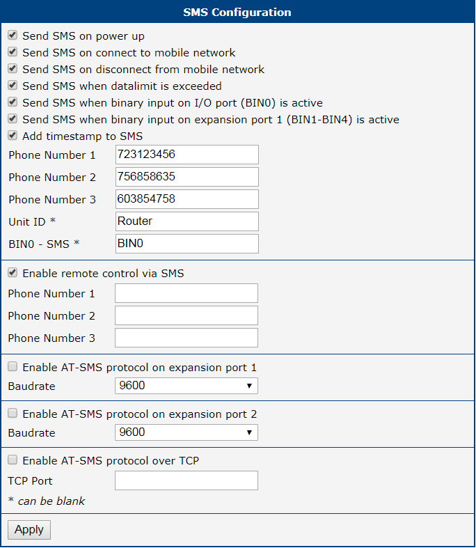
Example 2: Sending SMS via Serial Interface on the Port 1
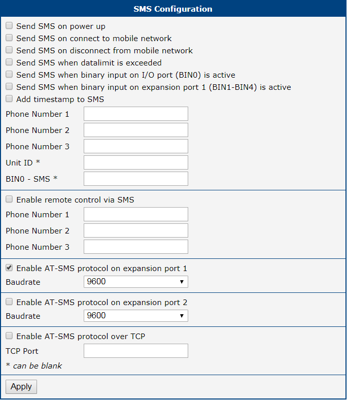
Example 3: Control the Router Sending SMS from any Phone Number
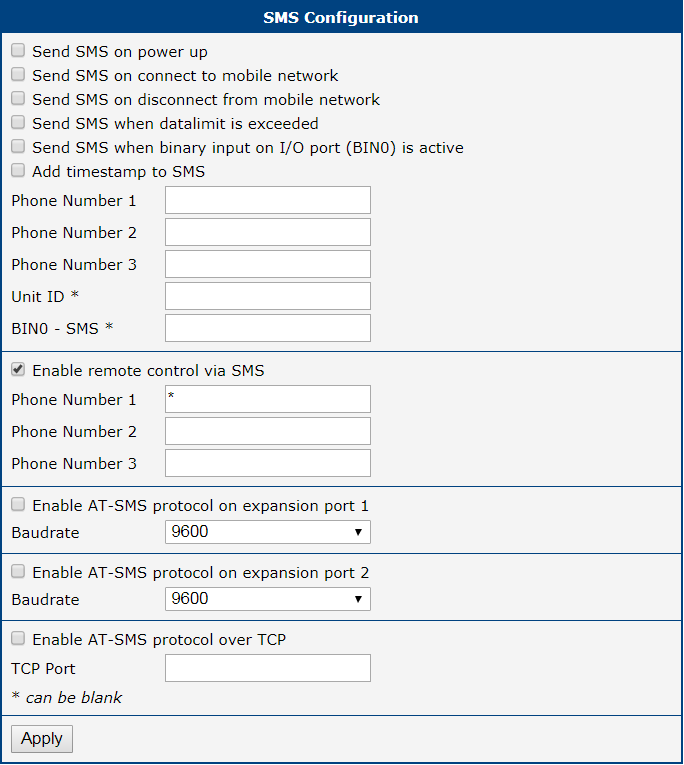
Example 4: Control the Router Sending SMS from Two Phone Numbers
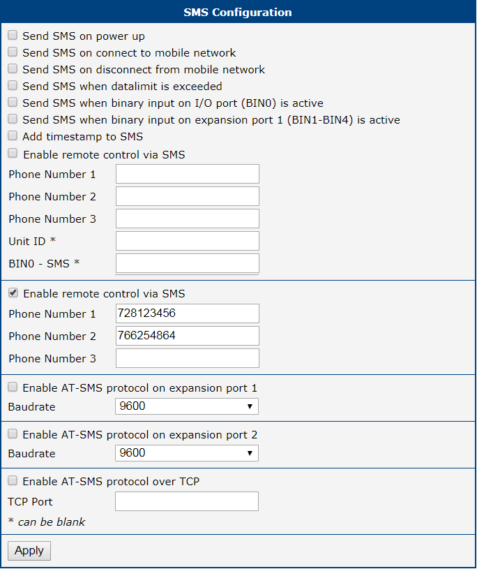
SSH
The Secure Shell (SSH) service allows for secure command-line access to the router's operating system. To configure the SSH server, navigate to Services → SSH.
Info
Only users assigned the Admin role are authorized to log in via SSH. Users with the standard User role cannot access the command line.
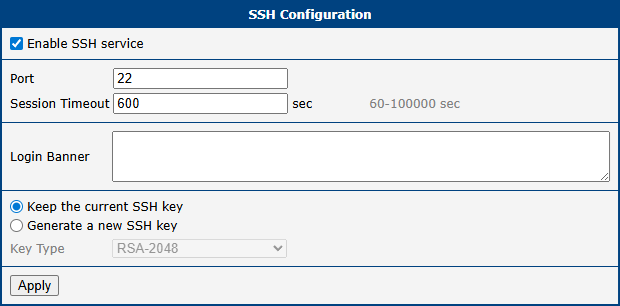
General Settings
| Item | Description |
|---|---|
| Enable SSH service | Enables or disables the SSH server on the router. |
| Port | The TCP port on which the SSH server listens for incoming connections. Default: port 22. |
| Session Timeout | The duration of inactivity (in minutes) after which an SSH session is automatically disconnected. |
| Login Banner | A custom message displayed to users before they are prompted for login credentials. |
Host Key Management
The SSH host key is a unique cryptographic key that clients use to verify the router's identity and prevent man-in-the-middle attacks.
Info
When you connect to the router via SSH for the first time, your client will prompt you to accept the host key's fingerprint. If the host key ever changes (e.g., after generating a new one), your client will display a security warning. This is expected behavior.
| Item | Description |
|---|---|
| Keep the current SSH key | Retains the existing host key. Recommended for normal operation. |
| Generate a new SSH key | Discards the current key and generates a new one. Typically used for security policy reasons only. |
| Key Type | The algorithm for the host key: ED25519 (modern, fast, and secure elliptic curve algorithm) or RSA (older, widely supported standard). |
Syslog
The Syslog service collects and manages system messages from the router's operating system and applications. To configure it, navigate to Services → Syslog.
The collected logs can be viewed at Status → System Log, or via the command line with the slog command.
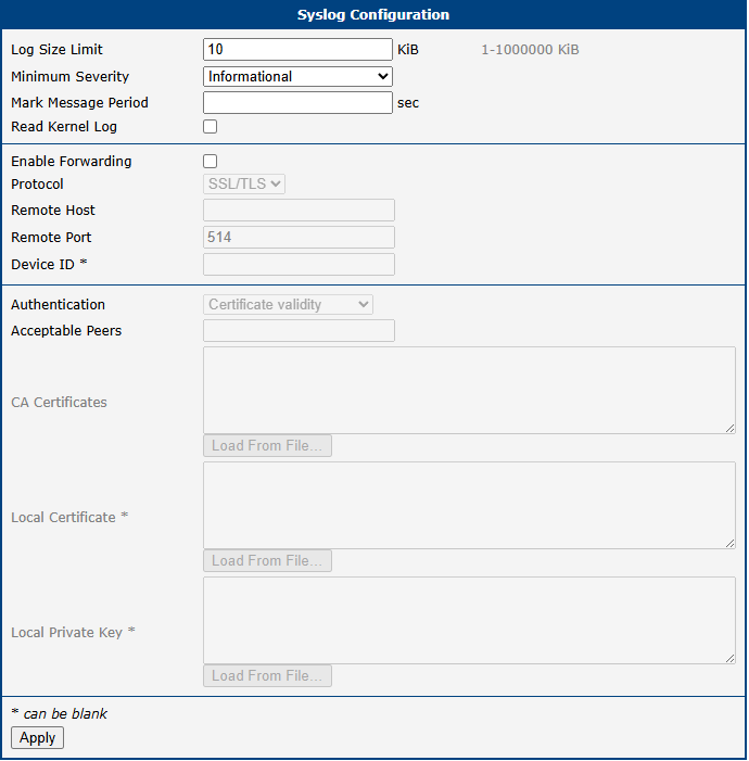
Info
Some items listed below are not available for ICR-2[0456]00 products.
| Item | Description |
|---|---|
| Log Size Limit | Sets the maximum size (in KiB) for the local log files. The default is 10 KiB. |
| Minimum Severity | Defines the minimum log severity level, ranging from Emergency to Debug. The Debug level offers detailed logs useful for troubleshooting but should be used only when necessary. Note: Some configuration pages (e.g., WiFi, IPsec, Authentication) or Router Apps may include separate logging level settings. |
| Mark Message Period | Defines the time interval during which the -- MARK -- string will be printed in the syslog, acting as a keepalive message. |
| Read Kernel Log | Enables retrieval of new log messages from /dev/kmsg. Check this option to forward kernel messages, such as device mounting notifications or firewall LOG target messages. Upon service (re)start, all existing kernel log entries will be sent to the remote server, potentially resulting in duplicate messages. Afterward, only new messages will be forwarded. |
| Enable Forwarding | Enables forwarding of syslog messages to a specified host capable of processing them. |
| Protocol | Selects the protocol used for forwarding: • UDP • TCP • SSL/TLS |
| Remote Host | Specifies the hostname or IP address of the remote host for real-time syslog forwarding. |
| Remote Port | Defines the port used for forwarding. |
| Device ID | A unique identifier for remote logging. If left blank, the default identifier Router is used. |
| Authentication | Configures the authentication method for the syslog server when using SSL/TLS. Options include: • None (encryption only) – Disables authentication for the receiver; communication remains encrypted. • Certificate fingerprint – Validates the server certificate fingerprint against Acceptable Peers. • Certificate validity – Accepts any server with a valid certificate signed by the specified CA. • Certified peer name – Checks the validity of the certificate and verifies the certified DNS names in the subjectAltName extension or the Common Name against Acceptable Peers. Note: The server may apply its own sender authentication settings, independent of this configuration. |
| Acceptable Peers | Specifies the accepted certificate fingerprint (SHA1) or DNS/Common Name of the remote peer. Wildcards are allowed, e.g., "*.example.net". Required if Authentication is set to Certificate fingerprint or Certified peer name. |
| CA Certificates | Provides the full certificate chain (CA certificates in PEM format) for validating remote certificates. Not required if Authentication is set to None. |
| Local Certificate | Specifies a certificate in PEM format, which must be authorized for TLS client authentication. |
| Local Private Key | Configures the local private key and certificate. This is optional if the server does not require transport sender authentication. |
Peripheral Ports
Info
Some interfaces may not be available for all models.
Configuration of physical interfaces such as RS-232, RS-485, USB serial converter, and digital Inputs/Outputs is accessible from Configuration → Peripheral Ports. Each interface is configured on its own subpage.
RS-232 Port
On the RS-232 Port configuration page, you can activate the port by ticking the Enable access over TCP/UDP checkbox. Additional settings are detailed in the table below. Support is provided for both IPv4 and IPv6 TCP/UDP client/server configurations.
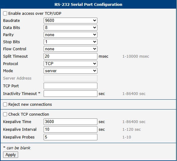
| Item | Description |
|---|---|
| Baudrate | Configurable communication speed: 300, 600, 1200, 2400, 4800, 9600 (default), 19200, 38400, 57600, 115200, 230400. |
| Data Bits | Number of data bits: 5, 6, 7, 8 (default 8). |
| Parity | Parity control bit: None (data sent without parity), Even (data sent with even parity), Odd (data sent with odd parity). |
| Stop Bits | Number of stop bits: 1 (default), 2. |
| Flow Control | Flow control method: None or Hardware. |
| Split Timeout | Time threshold for message segmentation. If the gap between two characters exceeds this value (in milliseconds), any buffered characters are sent over the network. |
| Protocol | Communication protocol: TCP (connection-oriented) or UDP (connectionless). |
| Mode | Connection mode for TCP: server (the router listens for incoming connections on the specified port) or client (the router initiates a connection to a remote server). |
| Server Address | When in client mode, the IP address or domain name of the remote server. Both IPv4 and IPv6 are supported. |
| TCP Port | The TCP/UDP port for communication. Applies to both server and client modes. |
| Inactivity Timeout | Time in seconds after which an inactive TCP/UDP connection is automatically terminated. |
| Reject new connections | When enabled, the router rejects new incoming connections while one is already active, enforcing a single-client connection. |
| Check TCP connection | When enabled, the router actively monitors the TCP connection using keepalive packets. |
| Keepalive Time | Time interval in seconds after which the router sends a keepalive probe to verify the connection. |
| Keepalive Interval | Time in seconds the router waits for a response to a probe before resending it. |
| Keepalive Probes | Number of unanswered probes before the connection is considered inactive. |
Ethernet-to-Serial Communication Example
This example demonstrates how to use the router as a gateway to connect a PC on an Ethernet network to a remote serial device. A PC at 192.168.1.100 sends data to the remote router (10.0.0.2) on TCP port 2000. The remote router is configured in TCP Server mode and listens for incoming connections. Once a connection is established, it forwards all data from the TCP socket to its RS-232 port, which is connected to the PLC. The first router (192.168.1.1) serves as the default gateway for the PC.
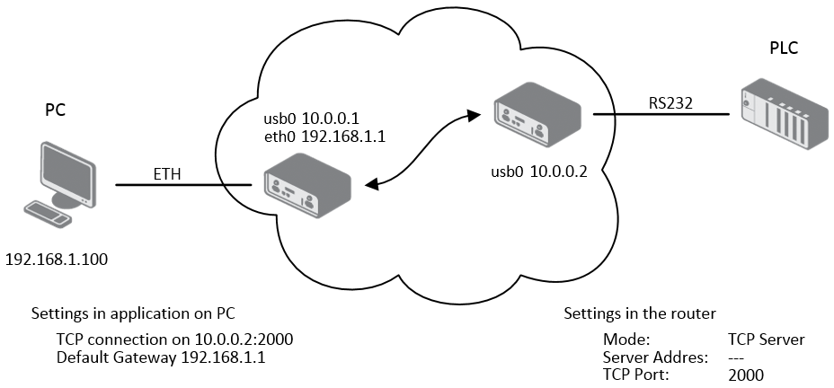
Serial Interface Communication Example
This example illustrates how to create a transparent serial tunnel over an IP network. The PC is connected via RS-232 to the first router (10.0.0.1), which is configured in TCP Client mode and initiates a connection to the second router (10.0.0.2) on port 2000. The second router, configured as a TCP Server, is connected to the PLC via its RS-232 port. Data from the PC is tunneled over the TCP connection to the second router and passed to the PLC.
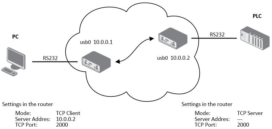
RS-485 Port
The RS-485 port configuration is analogous to the RS-232 port. The configuration items and their meanings are identical to those described in the RS-232 Port section.
Inputs/Outputs
Info
Starting from router firmware version 6.6.0, the USR LED settings on this page replace the original USR LED Management router app, and it is strongly recommended to use this built-in feature instead of the app.
On the Inputs/Outputs page, you can manually turn a digital output on or off and define the operation mode for the router’s USR LED. In the image below, Digital Output 0 is On and can be turned off by clicking the Off button. Conversely, Digital Output 1 is Off and can be turned on by clicking the On button.
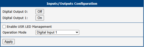
By enabling Enable USR LED Management, you can set the desired operation mode for the USR LED. The available modes are described in the table below:
| Item | Description |
|---|---|
| Always OFF | The LED is permanently off. |
| Always ON | The LED is permanently on. This is useful for physically locating the router among other devices. |
| Digital Input x | The LED lights when digital input x is On. The state is updated every 100 ms. |
| Digital Output x | The LED lights when digital output x is On. The state is updated every 100 ms. |
| RS-xxx Rx activity | The LED lights when the serial interface on peripheral port xxx is receiving data. |
| RS-xxx Tx activity | The LED lights when the serial interface on peripheral port xxx is transmitting data. |
| RS-xxx Rx and Tx activity | The LED lights when the serial interface on peripheral port xxx is receiving and/or transmitting data. |
| WiFi AP activity | The LED lights when a client is connected to the router’s Wi-Fi AP and flashes during communication. |
| WiFi STA activity | The LED lights when the router is connected to a remote Wi-Fi AP and flashes during communication. |
| OpenVPN activity | The LED lights when an OpenVPN tunnel is established and has received data. |
| IPsec active | The LED lights when an IPsec tunnel is established. |
| WireGuard activity | The LED lights when a WireGuard tunnel is established and has received data. |
| WebAccess/DMP active | The LED lights when the router is connected to a WebAccess/DMP server. |
System
The System configuration menu contains settings that are common to the entire router system, such as authentication, identification, and automatic updates.
Authentication
The Configuration → System → Authentication page allows for the configuration of user authentication methods, password policies, and account lockout settings. The router can authenticate users against its local database or against external RADIUS or TACACS+ servers.

General Settings
These settings are common across all authentication modes.
| Item | Description |
|---|---|
| Two-Factor Authentication | Enables a second layer of security for user logins. Options include Google Authenticator or OATH. |
| Mode | The primary authentication method: Local user database (router's local user list), RADIUS with fallback (RADIUS server; falls back to local if unreachable), RADIUS only (RADIUS server only; login is impossible if the server is unreachable), TACACS+ with fallback (TACACS+ server; falls back to local if unreachable), or TACACS+ only (TACACS+ server only; login is impossible if the server is unreachable). |
| Lock Account After | The number of failed login attempts before an account is locked. |
| Count Fails For | The time window in seconds during which failed attempts are counted. |
| Unlock After | The duration in seconds after which a locked account is automatically unlocked. |
| Force Password Complexity | Enforces minimum password strength requirements. The four character classes are: uppercase (A–Z), lowercase (a–z), digits (0–9), and special characters (e.g., !@#$+.). Levels: Good (min. 12 characters, 3+ classes, no 3 consecutive identical characters, no username, not a palindrome); Strong (min. 16 characters, all 4 classes, no 2 consecutive identical characters, no username, not a palindrome). |
| Expire Password After | The number of days until a user password expires, forcing a change on next login. |
| Delay After Fail | The time in seconds the login screen is disabled after a failed attempt. |
| Debug | Enables detailed authentication-related messages in the system log. |
RADIUS Mode
To use RADIUS for authentication, select either RADIUS with fallback or RADIUS only and configure the server details.
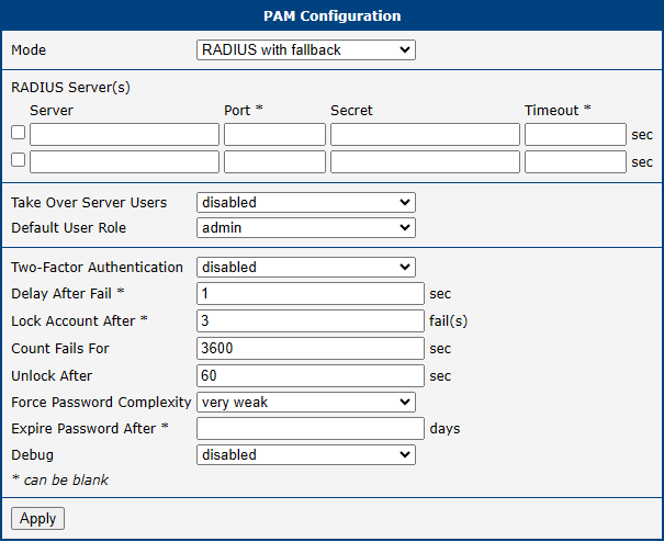
Warning
For a RADIUS user to log in, a corresponding user account must exist on the router locally. This account can be created manually (see User Management) or automatically by enabling the Take Over Server Users option.
| Item | Description |
|---|---|
| Server | The IP address of the primary and optional secondary RADIUS server. |
| Port | The UDP port of the RADIUS server (default: 1812). |
| Secret | The shared secret used to encrypt communication with the RADIUS server. |
| Timeout | The time in seconds to wait for a response from the RADIUS server. |
| Take Over Server Users | When enabled, a local user account is created automatically upon successful RADIUS authentication if one does not already exist. The account is created without a password. |
| Default User Role | Assigns a default role (Admin or User) to users created via the Take Over feature, unless overridden by the RADIUS server via the Service-Type attribute: Administrative-User assigns the Admin role; NAS-Prompt-User assigns the User role. |
TACACS+ Mode
To use TACACS+ for authentication, select either TACACS+ with fallback or TACACS+ only and configure the server details.
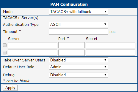
Warning
As with RADIUS, a corresponding local user account is required for TACACS+ authentication. This account can be created manually or automatically with the Take Over Server Users option, as detailed in User Management.
| Item | Description |
|---|---|
| Authentication Type | The authentication protocol to use: ASCII, PAP, or CHAP. |
| Timeout | The time in seconds to wait for a response from the TACACS+ server. |
| Server | The IP address of the primary and optional secondary TACACS+ server. |
| Port | The TCP port of the TACACS+ server (default: 49). |
| Secret | The shared secret used to encrypt communication with the TACACS+ server. |
| Take Over Server Users | When enabled, a local user account is created automatically upon successful TACACS+ authentication if one does not already exist. The account is created without a password. |
| Default User Role | Assigns a default role (Admin or User) to users created via the Take Over feature. |
Identification
The Configuration → System → Identification page allows you to define several strings used to identify the router. These values serve multiple purposes:
- The Name and Location strings are displayed in the top-right corner of the web interface.
- The Name, Location, Contact, and Custom fields are exposed via SNMP for remote monitoring, as detailed in SNMP.
Info
Previously, these settings were located on the SNMP configuration page. They have been moved here to serve as a central point for router identification.
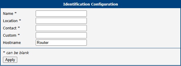
| Item | Description |
|---|---|
| Name | A custom name for the router (e.g., "Main Office Gateway"). Also used as the SNMP System Name (sysName). |
| Location | The physical location of the router (e.g., "Server Room A"). Used as the SNMP System Location (sysLocation). |
| Contact | Contact information for the person responsible for the device (e.g., an email address or phone number). Used as the SNMP System Contact (sysContact). |
| Custom | A custom string for any additional information. Used as the SNMP infoCustom field. |
| Hostname | The hostname of the router, used to identify the device on the local network (e.g., in DHCP leases). |
Automatic Update
The router can be configured to automatically download and apply firmware and configuration updates from a remote server or a local USB drive. This feature is essential for managing large-scale deployments and ensuring that devices are always up-to-date. The settings are located on the Configuration → System → Automatic Update page.
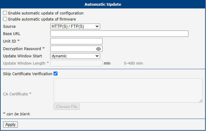
Update Configuration
| Item | Description |
|---|---|
| Enable automatic update of configuration | Enables the automatic update of the router's configuration file. |
| Enable automatic update of firmware | Enables the automatic update of the router's firmware. |
| Source | Specifies the location of the update files: HTTP(S)/FTP(S) server (updates are downloaded from the Base URL), USB flash drive (the router searches the root directory of a connected USB drive), or Both (the router checks both the remote server and a connected USB drive). |
| Base URL | The base URL of the remote server where update files are stored. The default protocol is HTTPS. To use a different protocol, specify the prefix explicitly (e.g., http://myupdateserver.com). |
| Unit ID | A custom identifier used as the filename for the configuration file. If empty, the router defaults to using its ETH0 MAC address as the filename. |
| Decryption Password | The password required to decrypt an encrypted configuration file. |
| Update Window Start | The hour (1–24) when the daily update check should begin. If set to dynamic, the check runs five minutes after boot and every 24 hours thereafter. |
| Update Window Length | A duration in minutes defining a window of time, starting at the Update Window Start, during which the update is performed at a random moment. This helps distribute load on the update server in large deployments. |
| Skip Certificate Verification | When enabled, the router does not validate the SSL/TLS certificate of the remote HTTPS/FTPS server. |
| CA Certificate | The custom CA certificate used for server validation. |
File Naming Conventions
The router looks for files with specific names on the update source. All files must be in a tar.gz archive.
- Firmware: The firmware filename is composed of the router model and a
.binextension (e.g.,icr-440x.bin). The exact filename can be found on the Administration → Update Firmware page. A corresponding version file (*.ver) must also be present on the server. - Configuration: The configuration filename is determined by the Unit ID. If specified, that value is used as the filename (e.g.,
test.cfg). If left blank, the router looks for a file named after its ETH0 MAC address, with colons replaced by dots (e.g.,00.11.22.33.44.55.cfg).
Warning
- Always upload both the
*.binand*.verfiles to the server for firmware updates. If the*.verfile is missing and the server returns an incorrect success code, the router may enter a continuous download loop. - Firmware updates may introduce incompatibilities with installed router apps. Always check the application notes for compatibility information and update router apps as needed.
- The automatic update process will always run five minutes after a manual firmware upgrade, regardless of the scheduled time.
Configuration Examples
Example 1: Scheduled Update
In this example, an ICR-4401 router is configured to check for a new firmware or configuration file daily at 1:00 AM from a specific URL.
- Firmware URL:
https://example.com/icr-440x.bin - Configuration URL:
https://example.com/test.cfg
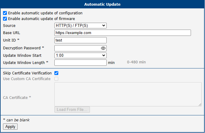
Example 2: Update Based on MAC Address with Encrypted Configuration
This example shows an ICR-4161 router configured to check for updates within a two-hour window. The configuration file is encrypted and identified by the router's MAC address.
- Firmware URL:
https://example.com/icr-416x.bin - Configuration URL:
https://example.com/00.11.22.33.44.55.cfg
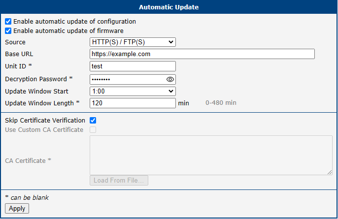
Events
Info
Starting with firmware version 6.6.0, this functionality replaces the legacy Event Notificator Router App. It is strongly recommended to use this built-in feature instead of the old Router App.
The Configuration → Events page provides a powerful system for triggering automated actions in response to specific system events. This feature allows you to create custom notifications and responses for monitoring the router's status and health.
To begin, check the Enable events notifications box at the top of the page.
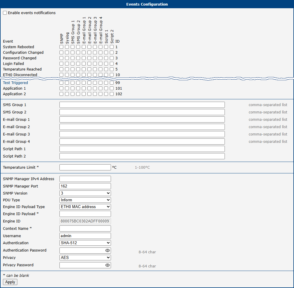
Event-Action Matrix
The core of this feature is the matrix, which links system events (rows) to specific actions (columns). When a particular event occurs, the router checks this matrix and executes all the actions that are checked in that event's row.
| Event | Description |
|---|---|
| System Rebooted | Triggered when the router finishes its boot sequence. |
| Configuration Changed | Triggered whenever the router's configuration is modified and saved. |
| Password Changed | Triggered when a user password is changed. |
| Login Failed | Triggered after any unsuccessful login attempt to the router, either via the web interface or an SSH connection. |
| Temperature Reached | Triggered when the internal temperature exceeds the limit defined in the Temperature Limit field. |
| ETHx Disconnected | Triggered when the link on the corresponding Ethernet port is lost. |
| Test Triggered | A virtual event designed specifically for testing configured actions (e.g., to verify that an SMS or email is sent correctly). Note: Before testing, ensure that the event system is enabled, the desired actions are configured, and all settings are saved. The test can be triggered manually by clicking on the event name in the web interface. |
| Application 1/2 | Custom events that can be triggered by user scripts or applications (IDs 101 and 102). |
| Action | Description |
|---|---|
| SNMP | Sends an SNMP trap to the defined SNMP manager. |
| Syslog | Writes a message to the system log. |
| SMS Group 1/2 | Sends an SMS to all numbers in the specified SMS group. |
| E-mail Group 1–4 | Sends an email to all addresses in the specified email group. |
| Script 1/2 | Executes the user script located at the specified path. |
Action Definitions
This section is where you define the details for each action.
| Item | Description |
|---|---|
| SMS Group 1/2 | A comma-separated list of phone numbers for the respective SMS action group. |
| E-mail Group 1–4 | A comma-separated list of email addresses for the respective email action group. |
| Script Path 1/2 | The absolute path to the user script to be executed (e.g., /var/scripts/my_script.sh). |
| Temperature Limit | The temperature threshold in degrees Celsius (°C) for the Temperature Reached event. |
SNMP Settings
This section contains the specific settings for the SNMP trap action.
| Item | Description |
|---|---|
| SNMP Manager IPv4 Address | The IP address of the server that will receive the SNMP traps. |
| SNMP Manager Port | The UDP port on which the SNMP manager is listening. The default is 162. |
| SNMP Version | The version of the SNMP protocol to use. Version 3 is recommended for enhanced security. |
| PDU Type | The type of Protocol Data Unit to send. Inform requires an acknowledgment from the manager, while Trap does not. |
| Community | For SNMPv2c only. A password-like credential used to authenticate communications. This string must exactly match the community string configured on the SNMP manager. |
| Engine ID Payload Type | Determines the source for generating the Engine ID. Options include the ETH0 MAC address, a custom ASCII Text string, or a custom Hexadecimal Value. |
| Engine ID Payload | If the Payload Type is set to ASCII or Hexadecimal, enter the custom value to be used for the Engine ID. |
| Engine ID | The final, unique identifier for the SNMP engine on this device, generated based on the settings above. This field is read-only. |
| Context Name | An identifier used to group related SNMP data, allowing for different logical subsets of managed objects. |
| Username | The username for SNMPv3 authentication. |
| Authentication | The hashing algorithm used for SNMPv3 message authentication (e.g., SHA-512). |
| Authentication Password | The password for SNMPv3 authentication. |
| Privacy | The encryption algorithm used for SNMPv3 message privacy (e.g., AES). |
| Privacy Password | The password for SNMPv3 privacy. |
Scripts
Warning
Scripting is not supported on S1 platform routers. The recommended alternative is to create a custom Router App. For more information, refer to the Extending Router Functionality Application Note.
Quick Setup
The Quick Setup page provides a streamlined, single-page interface that gathers all of the most critical settings for the initial configuration of the router. This page is automatically displayed upon the first login to a new or factory-reset device, but it can also be accessed manually at any time via Configuration → Quick Setup.
This wizard conveniently consolidates essential settings from various sections of the web interface, allowing you to configure time, LAN, and mobile network settings from a single page.
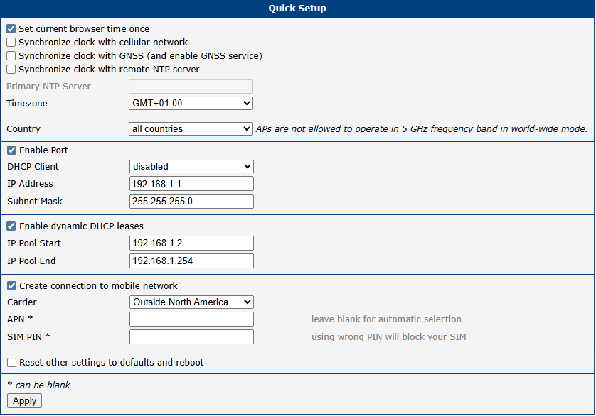
Time and Region
For a complete overview of these settings, refer to NTP and the Wi-Fi country configuration.
| Item | Description |
|---|---|
| Set current browser time once | A one-time action that sets the router's system time to match the time of your web browser. |
| Synchronize clock with... | Selects the method for automatic time synchronization. Note that synchronization via GNSS is only available on router models equipped with a GNSS module. |
| Primary NTP Server | The address of the NTP server to use when Synchronize clock with remote NTP server is selected. |
| Timezone | Sets the local timezone for the router. |
| Country | Configures the regulatory domain for Wi-Fi. Select the country of operation to ensure compliance with local radio frequency regulations, as this affects which Wi-Fi channels are available. |
LAN Port and DHCP Server
The full configuration options for the LAN interface are described in Ethernet.
| Item | Description |
|---|---|
| Enable Port | Enables or disables the primary LAN port (eth0). |
| DHCP Client | If enabled, the router's LAN port requests an IP address from another DHCP server on the network. |
| IP Address | The static IPv4 address assigned to the router's primary LAN interface. |
| Subnet Mask | The subnet mask for the primary LAN interface. |
| Enable dynamic DHCP leases | Enables the router's built-in DHCP server, which automatically assigns IPv4 addresses to client devices on the LAN. |
| IP Pool Start | The starting address of the IP range that the DHCP server leases to clients. |
| IP Pool End | The ending address of the IP range that the DHCP server leases to clients. |
Mobile Network
Info
This section is only available on cellular router models.
The complete configuration for the mobile network is available in Mobile WAN.
| Item | Description |
|---|---|
| Create connection to mobile network | When checked, the router automatically attempts to connect to the mobile network after booting. |
| Carrier | Allows the selection of a pre-defined profile for a specific mobile carrier (e.g., for North American operators). |
| APN | The Access Point Name for your mobile network data plan. In many cases, this can be left blank to allow for automatic selection by the carrier. |
| SIM PIN | The PIN for your SIM card. Entering an incorrect PIN multiple times may permanently block the SIM card. |
System and Service Settings
| Item | Description |
|---|---|
| Reset other settings to defaults and reboot | If checked, any settings not present on this Quick Setup page are reset to their factory defaults when the new configuration is applied. |