GRE Tunnel
GRE Protocol
Generic Routing Encapsulation (GRE) is a tunneling protocol developed by Cisco Systems that encapsulates a wide variety of network layer protocols inside virtual point-to-point links over an Internet Protocol internetwork. A GRE tunnel connects two LANs as if they were a single, homogeneous network. GRE is used to send IP packets from one network to another without the intervening routers parsing or treating them as IP packets.
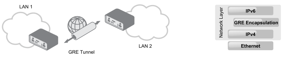
GRE encapsulates the original (inner) packet intended for delivery to the remote network into an outer packet. This outer packet is transmitted through the GRE tunnel, with intervening routers routing it as a standard IP packet until it reaches the destination network, where the outer packet is removed and the original packet is forwarded to its target. Unlike an IP-to-IP tunnel, a GRE tunnel can transport multicast and IPv6 packets between connected networks. The figure below graphically displays the principle of the GRE tunnel (on the left) and an example of encapsulating IPv6 packets for transport through an IPv4 network (on the right).
GRE protocol advantages: GRE tunnels encapsulate multiple protocols over a single-protocol backbone, provide workarounds for networks with limited hops, connect discontinuous sub-networks, and allow VPNs across wide area networks (WANs).
Examples of GRE protocol usage: GRE can be used with PPTP to create VPNs, in conjunction with IPsec VPNs to pass routing information between connected networks, and in mobility protocols. Linux and BSD systems can also establish ad-hoc IP over GRE tunnels that interoperate with Cisco equipment.
Tips
GRE protocol provides a stateless private connection, but it is not encrypted (secured). It does not use any encryption—such as ESP (Encapsulating Security Payload) in IPsec—and is specified in RFC 2784 and RFC 2890. It is identified by the number 47 in the Protocol field of the IP header.
GRE Tunnel Configuration
You can configure up to four GRE tunnels. To open the GRE tunnel configuration page, click the GRE menu item in the Configuration section. The menu expands to reveal four separate configuration pages: 1st Tunnel, 2nd Tunnel, 3rd Tunnel, and 4th Tunnel.
Tips
Only IPv4 tunnels are supported in Advantech routers.
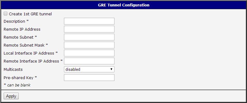
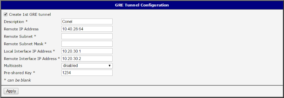
There are several settings available for each of the four GRE tunnels shown in the figure above. To activate a tunnel, check the Create 1st GRE tunnel option. The available settings are as follows:
| Item | Description |
|---|---|
| Description | Optional description of the tunnel. |
| Remote IP Address | IP address of the remote side of the tunnel. |
| Local Interface IP Address | IP address of the local side of the tunnel. |
| Remote Interface IP Address | IP address of the remote side of the tunnel. |
| Remote Subnet | IP address of the network behind the remote side of the tunnel. |
| Remote Subnet Mask | Mask of the network behind the remote side of the tunnel. |
| Multicasts | Enables/disables multicast: • disabled — multicast disabled • enabled — multicast enabled |
| Pre-shared Key | An optional value that defines the 32-bit shared key in numeric format, which allows filtered data to pass through the tunnel. This key must be identical on both routers; otherwise, received packets are dropped. Using this key does not provide tunnel security. |
All changes are applied after pressing the Apply button.
Caution
Attention: GRE tunnel does not connect through NAT by itself. If you need to create a tunnel through NAT, use an IP-to-IP tunnel (where IP packets are encapsulated within IP packets) or GRE over IPsec (a secured IPsec tunnel with GRE encapsulation inside it).
GRE Configuration Examples
Advantech Routers
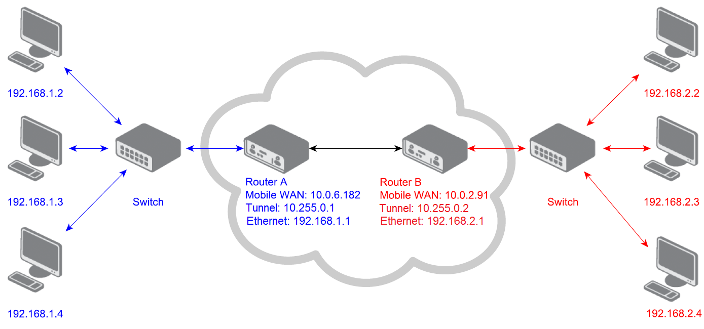
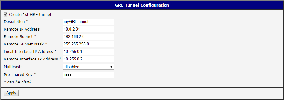
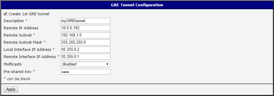
This example demonstrates how to connect two LANs using a GRE tunnel between two Advantech routers. The default gateway for devices in the blue network is Router A, while for devices in the red network it is Router B. GRE tunnel parameters for both routers are shown in the following figures:
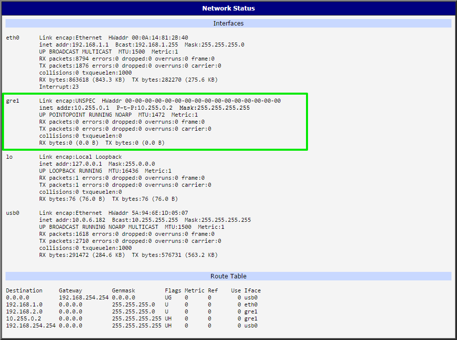
After activating the GRE tunnel, a new network interface, gre1, is created on each router. You can view this interface in the Network section under Status — see the figure below:
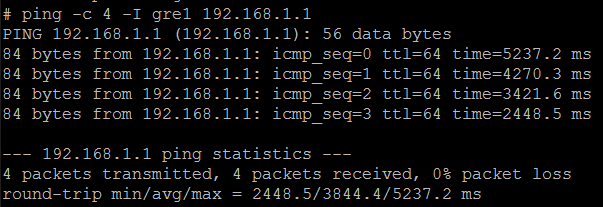
The GRE tunnel should now be operational, allowing connectivity between the networks. You can verify this using the ping program from one of the routers (accessed via telnet or SSH). In the figure below, the console of Router B (192.168.2.1) displays the ping command and its output. The -c switch specifies the number of requests, and the -I switch specifies the interface (gre1).
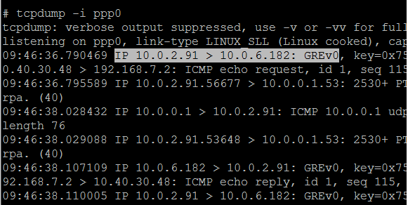
To further verify GRE protocol usage, you can run the tcpdump program on one of the routers for packet analysis. In the next figure, the marked row (GREv0) indicates that tcpdump was executed with the -i switch to specify the network interface (in this case, ppp0, which monitors Mobile WAN communication).
Advantech Router and OS Linux
This example shows a GRE tunnel configuration between an Advantech router and an OS Linux system. Since Linux is also running on the Advantech router, the configuration is straightforward.
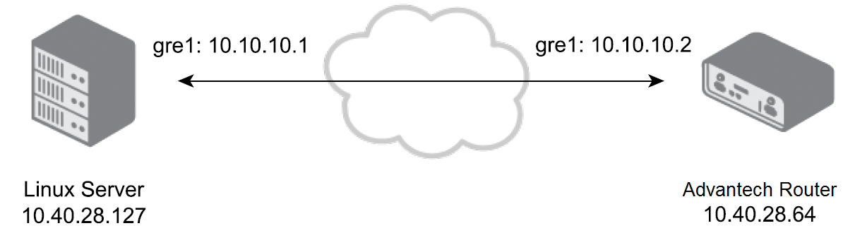
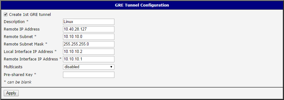
For the topology and IP addresses in this example, configure the GRE tunnel on the Advantech router as shown below:
On the OS Linux side, open a terminal and configure the other end of the GRE tunnel as follows. First, verify that the Linux kernel module for GRE is loaded by running these commands:
sudo modprobe ip_gre
lsmod | grep gre
If the gre module is loaded, the output will resemble:
ip_gre                  22432  0
gre                      12989  1 ip_gre
Now, create the GRE tunnel using the following commands:
sudo ip tunnel add gre1 mode gre remote 10.40.28.64 local 10.40.28.127 ttl 255
sudo ip link set gre1 up
sudo ip addr add 10.10.10.1/24 dev gre1
You can verify the tunnel's creation by running the ip route show command, which displays routing rules for the new gre1 interface. Additionally, the ifconfig command will show the newly created interface. To shut down or delete the GRE interface, use these commands:
sudo ip link set gre1 down
sudo ip tunnel del gre1
These commands can also be executed on the Advantech router (via SSH or telnet) since OS Linux is running on the router and the ip program is available. For more details, refer to the Command Line Interface application note.
Advantech Router and Cisco Router
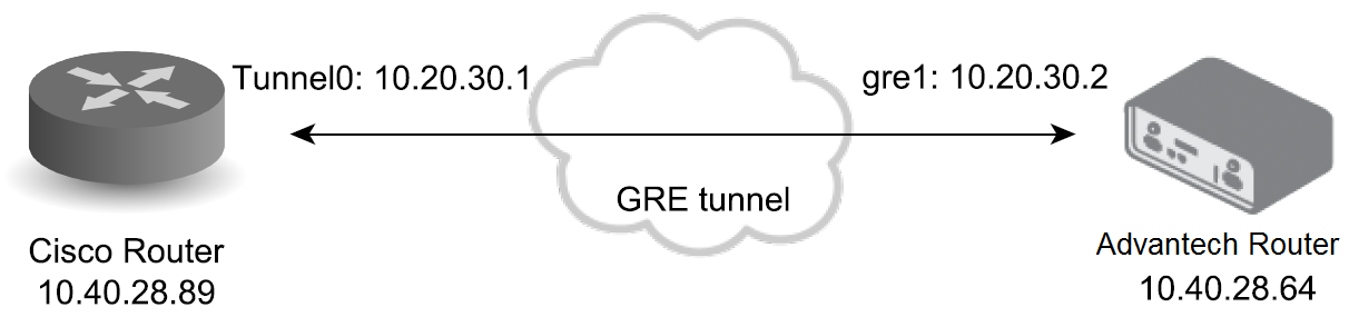
This example demonstrates the GRE tunnel configuration between an Advantech router and a Cisco router. The topology and IP addresses are illustrated in the figure below:
Configure the Advantech router as shown:
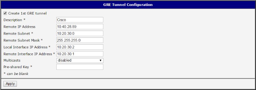
Log into the Cisco router's console (via telnet or serial connection) and enter the configuration terminal by typing the config terminal command. Then, create the GRE tunnel using the following commands:
Router(config)# interface Tunnel0
Router(config-if)# ip address 10.20.30.1 255.255.255.0
Router(config-if)# tunnel source 10.40.28.89
Router(config-if)# tunnel destination 10.40.28.64
Router(config-if)# end
Optionally, adjust the packet length to account for the added overhead and prevent packet fragmentation. You can also add a route for devices connected behind the router:
Router(config-if)# ip mtu 1400
Router(config-if)# ip tcp adjust-mss 1360
Router(config)# ip route 192.168.1.0 255.255.255.0 10.20.30.1
You can view the running configuration by typing the show running-config command (outside the configuration terminal). The Tunnel0 interface should be present and configured as shown. For more detailed Cisco router settings, consult the Cisco documentation.
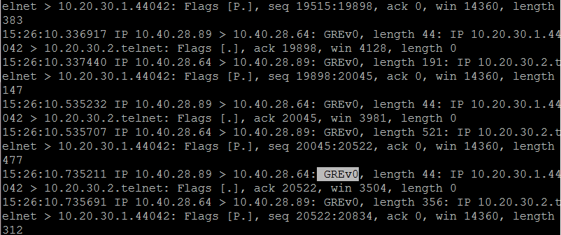
Once configured, the ping command should succeed (from the Cisco router to the Advantech router via the GRE tunnel — targeting the 10.20.30.2 address and vice versa). To verify GRE encapsulation, log into the Advantech router (via telnet or SSH) from the Cisco router's console and run the tcpdump program for packet analysis. The captured packets will include a GRE protocol marker, as shown in the next figure:
GRE over IPsec Tunnel
This example illustrates how to create a GRE tunnel within an IPsec tunnel between two Advantech routers. This secured (encrypted) connection can transport routing information between networks.
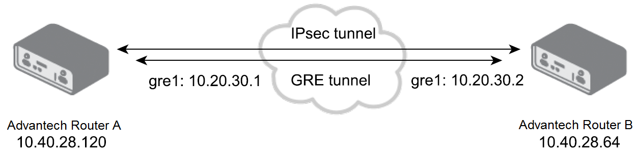
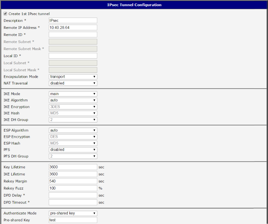
For GRE over IPsec, establish the IPsec connection first, then set up the GRE tunnel on both routers. The following figures show the IPsec and GRE configurations for Router A and Router B:
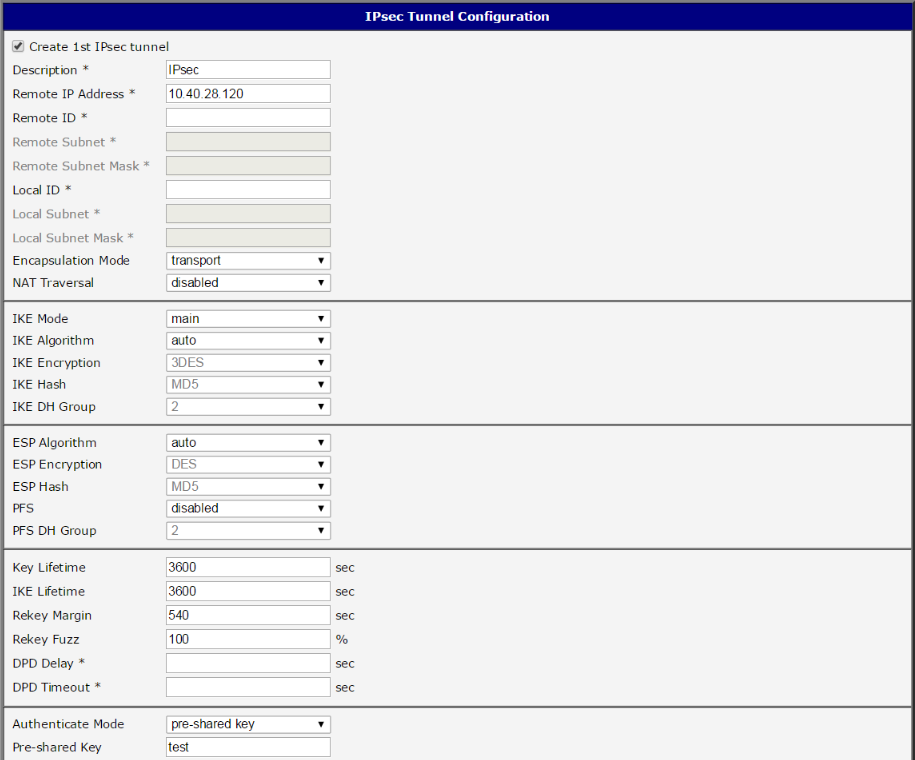

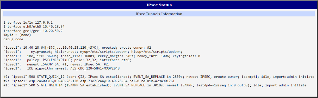
When configured correctly, both routers display an established status in the IPsec section under Status (and in the System Log).
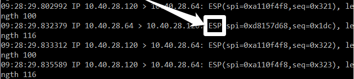
To verify that the GRE tunnel is encrypted by IPsec, log into both routers via telnet or SSH. For example, on Router B, run the tcpdump program with parameters to filter for the ESP protocol (IPsec):
tcpdump -s0 protochain 50Then, from Router A, log into Router B via telnet or SSH through the GRE tunnel (using the 10.20.30.2 address) so that the captured traffic is from the GRE tunnel. As commands are executed on Router A, the tcpdump output on Router B will display the encrypted ESP packets. This confirms that communication through the GRE tunnel is encrypted via IPsec.