Modbus
Introduction
Modbus is a widely used communication protocol in industrial automation and control systems. It uses a simple request-response model, making it relatively straightforward. Modbus is compatible with various communication mediums, including serial interfaces (RS-232 and RS-485) and Ethernet connections. The Modbus protocol employs multiple types of data storage and access.
- Coils: 1-bit data, support reading and writing.
- Discrete Inputs: 1-bit data, read-only.
- Holding Registers: 16-bit data, support reading and writing.
- Input Registers: 16-bit data, read-only.
In a typical Modbus setup, a master device (e.g., a PC or a router) communicates with one or more slave devices (e.g., sensors, actuators, or other control devices). The master sends requests to read or write data to the slaves, and the slaves respond accordingly. Each data point in a device (coils, registers) is assigned a unique address, which the master uses to access and manipulate the data.
Function Codes
Function codes serve as identifiers for the operation the master device wants to perform on the slave devices.
Read Functions
1 - Read Coil Status
2 - Read Input Status
3 - Read Holding Registers
4 - Read Input Registers
Read requests include the starting address and the number of coils/registers to be read.
Write Functions
5  - Force Single Coil
6  - Preset Single Register
15 - Force Multiple Coils
16 - Preset Multiple Registers
Functions 5 and 6 set a specified value at a specified address. Functions 15 and 16 take a starting address, the number of registers to write, the number of data bytes to follow, and the values to be written.
Polling Interval
The polling interval is the time gap between successive master requests to slave devices. It affects data retrieval frequency and system responsiveness.
- Short polling interval: Frequent data fetch providing real-time or near-real-time updates, but may increase network traffic and potentially overload the slave devices.
- Longer polling interval: Reduced network traffic with slightly delayed updates and control system response.
In practice, the optimal interval typically ranges from 100 to 1000 milliseconds, ensuring real-time updates and efficient network use.
Serial Communication (RTU)
Used for communication over RS-232 or RS-485 interfaces. The following parameters must be configured:
- Baudrate — speed at which data is transmitted;
9600by default. - Data Bits — number of bits used to represent each character;
8by default. - Parity — simple error-checking mechanism;
noneby default. - Stop Bits — signal the end of a data character to ensure synchronization;
1by default. - Expansion port — port on the master device (e.g., the Advantech router); PORT1 for RS-232, PORT2 for RS-485. Refer to the General page in the router's settings or the Expansion Port 1/2 pages to locate the serial interface.
Ethernet Communication (TCP)
Modbus TCP encloses communication messages within TCP/IP packets, enabling device interaction based on IP addresses and ports. The primary parameter to configure is the TCP port. Port 502 is commonly used for Modbus TCP, allowing multiple devices to share a network.
Getting Data from Sensors
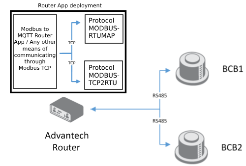
The master device should initiate the connection and requests to the slaves. Advantech Router Apps can handle this connection. Two router apps are available:
- Protocol MODBUS-RTUMAP Router App — Maps configured coils/registers from a connected Modbus slave to a Modbus TCP buffer inside the router. Acts as a security measure by mapping only specific coils/registers. Supports reading only; reading is configured via Meters inside the router app.
- Protocol MODBUS-TCP2RTU Router App — More flexible solution where the user defines the mapping between the Modbus slave and the Modbus TCP buffer. Works by forwarding TCP requests to the buffer, which translates them to serial requests. Supports both reading and writing.
Protocol MODBUS-RTUMAP
A configured router periodically reads data from sensors connected via the serial port and stores them in the router buffer, which a Modbus TCP connection can then access.
The following figure shows an example configuration for reading temperature, humidity, and dew point from a Temperature and Humidity Sensor.
Protocol MODBUS-RTUMAP Configuration
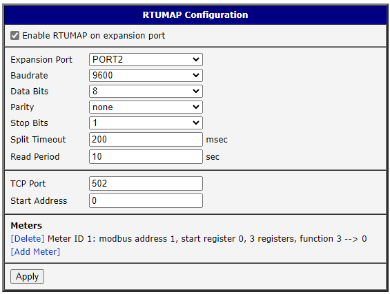
Enable RTUMAP on the expansion port to turn on the router app. Then configure the connected device by selecting the expansion port to which the Modbus device is connected and set the device parameters (Baudrate, Data Bits, Parity, and Stop Bits) from the device datasheet.
The Split Timeout variable is the delay between readings — increase it if the connected device cannot meet the requests. The Read Period variable is the period between readings to renew the values in the router app buffer.
In the TCP configuration, set only the TCP port of the Modbus slave to which the router app will write the values. This module creates a new Modbus TCP slave; mapping to an existing Modbus TCP slave is not possible.
The Start Address parameter is the starting address of the Modbus register to which the router app will write. It is the relative address of the four coils/registers. To write to absolute address 40000 (relative address 0 in holding registers), provide the value 0.
Meters Configuration
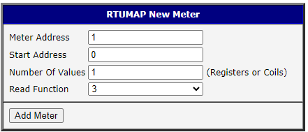
Set Meter Address to 1 unless more Modbus devices are connected to the same serial network.
Start Address is the relative starting address of the coils/registers to be read from the connected serial device. Use this together with Number Of Values, which specifies the number of coils/registers to read from the starting address.
Supported read functions:
1 - Read Coil Status
3 - Read Holding Registers
4 - Read Input Registers
After clicking [Add Meter], the meter appears in the Meters section of the router app. The number after the --> arrow indicates the starting coil/register to which the values will be mapped in the Modbus TCP slave.
Protocol MODBUS-TCP2RTU
Converts Modbus TCP requests from the router to Modbus RTU requests sent to the sensor. The user must create their own Modbus TCP requests; responses are returned to the TCP connection used for sending.
The following figure shows an example configuration for reading temperature, humidity, and dew point from a Temperature and Humidity Sensor.
Modbus-TCP2RTU Configuration
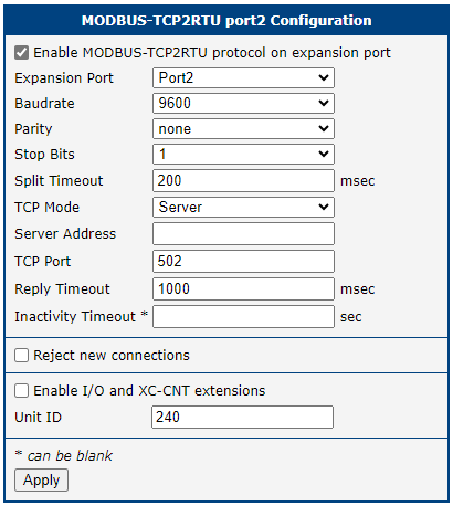
Enable the MODBUS-TCP2RTU protocol on the expansion port to turn on the router app. Then configure the connected device by selecting the expansion port and setting the device parameters (Baudrate, Data Bits, Parity, and Stop Bits) from the device datasheet.
Split Timeout — delay between readings. If the router receives two readings within this period, they merge and cause an error.
TCP Mode Server is the default mode. The TCP Port variable is for the Modbus slave to which requests will be sent. Read and write queries sent to this buffer are redirected to the configured Modbus slave device on the serial connection. This module creates a new Modbus TCP slave; mapping to an existing slave is not possible.
Increase Reply Timeout if requests fail due to timeouts. Leave Inactivity Timeout blank in most cases — set a value only if you want the router app to time out; to restart it after a timeout, restart the router app.
The Reject new connections checkbox limits the buffer to one connection — any new connection after the first is rejected.
Creating Modbus TCP Requests
With the router able to communicate with serially connected Modbus devices via the router apps, several options are available to manipulate and transmit this data:
- Modbus to MQTT Router App — Converts Modbus data from the Modbus TCP buffer and sends it to an MQTT Broker.
- Node-RED Modbus Node Router App — Modbus data manipulation inside Node-RED. Can directly access connected RTU devices.
- Python3 with pip Router App — Connect to the TCP connection from anywhere in the network using the router's IP address and the configured port. Uses the pymodbus library. Can directly access connected RTU devices.
- Third-party applications — Access Modbus data from anywhere in the same network as the router by providing the IP address and port.
Modbus to MQTT
Tips
Setting up Protocol MODBUS-RTUMAP or Protocol MODBUS-TCP2RTU is required before configuring this router app.
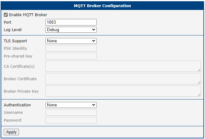
Periodically reads requests from the specified Modbus slave and publishes the responses to an MQTT Broker. If you do not have an MQTT Broker set up, use the MQTT Broker Router App — basic configuration requires only enabling the MQTT Broker.
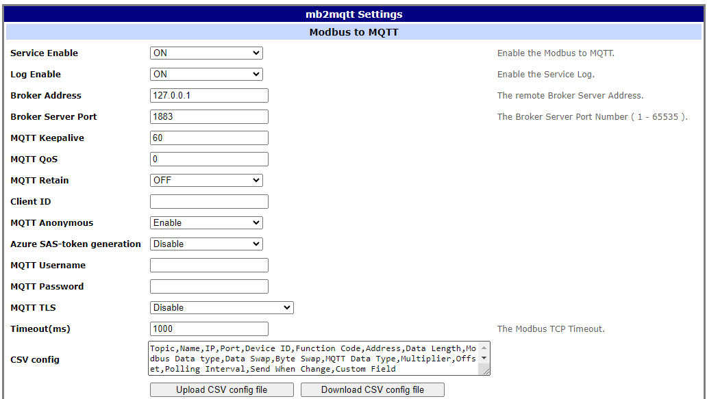
A .csv file is required to configure the Modbus to MQTT Router App. The file header must be in the following format:
Topic,Name,IP,Port,Device ID,Function Code,Address,Data Length,Modbus Data type,Data Swap,Byte Swap,MQTT Data Type,Multiplier,Offset,Polling Interval,Send When Change,Custom FieldRefer to the Modbus to MQTT Router App Application Note for more information.
An example row for converting Modbus protocol to MQTT:
temp,DI2,127.0.0.1,502,1,3,1,1,Integer,None,FALSE,Float,0.01,0,1000,No,0The .csv file in Excel looks like this:

Tips
Address 1 inside the .csv file accesses the holding register value stored at absolute address 40000 (relative address 0).
To run the Modbus to MQTT router app, set Service Enable to ON and upload the configuration by clicking [Upload CSV config file].
Node-RED
Node-RED is a versatile flow-based programming tool that provides a visual interface for wiring together devices, APIs, and online services. Its key strength is the ability to integrate a wide range of devices, protocols, and services — not limited to Modbus alone. Users can build complex automation and IoT solutions by combining Modbus communication with other services, APIs, databases, and hardware.
A simple request for getting data can be created by deploying the following flow:

After configuring the connection to a sensor, the value is read, divided by 1000, and output to the debug console.
More examples can be found in the Node-RED Application Note.
Python
Tips
Python runs on the PC connected to the router via Ethernet. The Modbus RTU slave is connected to the router via the serial port. A properly configured Protocol MODBUS-RTUMAP or Protocol MODBUS-TCP2RTU router app must be deployed on the router.
A simple TCP request for getting data using the pymodbus library:
from pymodbus.client import ModbusTcpClient

server_ip_address = '192.168.1.1'  # IP address of the router
server_port = 502                  # configured TCP port

client = ModbusTcpClient(host=server_ip_address, port=server_port)
if client.connect():
    print('Connected to Modbus TCP server')

result = client.read_holding_registers(address=0, slave=1, count=3)

# prints values from the first three registers
print(result.registers)
More Python examples can be found here.
Third-Party Applications
For SCADA applications, the setup is mostly the same. As an example, QModMaster is used here. To set up a TCP connection with the router, provide the router's IP address and the configured port.
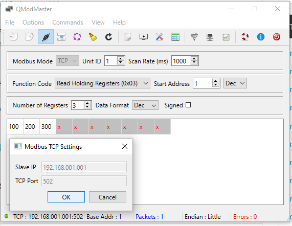
After successful configuration and selecting Modbus Mode: TCP, connect with the Connect button. Fill in the desired Start Address and Number of Registers, then click the Read / Write button.
The router app is required because you cannot connect directly from the PC to the sensor — the sensor is connected to the router via a serial connection, and the router is connected to the PC via TCP.
Handling Modbus RTU Queries Sent to the Router
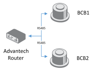
In more advanced networks, converting sensor data from RTU to TCP first is not necessary. The following network architecture can be deployed instead:
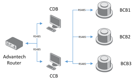
Here, the sensors (slaves, marked BCB in the figure) are queried by a serially connected device in the middle (master, CCB), which sends read requests to the connected sensors. CCB also sends Modbus RTU write requests to the Advantech Router, which acts as a Modbus slave. The Protocol MODBUS-RTU2TCP Router App converts these RTU write requests to TCP write requests.
Protocol MODBUS-RTU2TCP
Converts Modbus RTU requests from connected Modbus master devices to Modbus TCP requests for the router. Useful in setups where a device already creates requests to read from Modbus slaves and is connected to the router — this device sends Modbus requests to the router via the serial connection.
Modbus-RTU2TCP Configuration
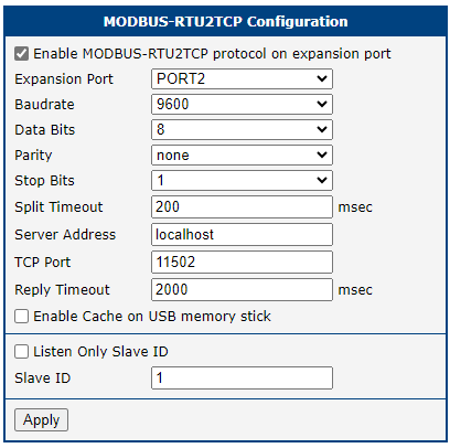
Enable the Modbus-RTU2TCP protocol on the expansion port to turn on the router app. Then configure the connected device by selecting the expansion port and setting the device parameters (Baudrate, Data Bits, Parity, and Stop Bits) from the device datasheet.
Split Timeout — delay between readings. If the router receives two readings within this period, they merge and cause an error.
Server Address and TCP Port are for the Modbus TCP slave. You must create or connect to a Modbus slave to which the serial requests will be sent. Read and write queries from the serial connection are redirected to the configured Modbus slave device on the TCP connection.
Increase Reply Timeout if requests fail due to timeouts.
Creating Example Modbus RTU Requests (from PC)
The PC is connected to the router via an Ethernet cable; the sensor is connected to the router via a serial port.
In SCADA applications, set up an application that periodically sends RTU write requests to the router. This example uses QModMaster. Set up an RTU connection with the router using the serial port of the router and the configured parameters.
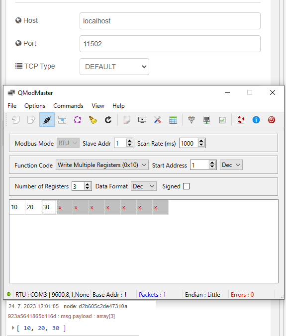
After successful configuration and selecting Modbus Mode: RTU, connect with the Connect button. Fill in the desired Start Address and Number of Registers. In this example, writing multiple registers is used — click the Read / Write button.
Setting up your own Modbus slave (to which the router app will send the requests) is required. In this example, a Modbus slave (server) was created inside the Node-RED module. Examples of reading and writing Modbus data in Node-RED can be found in the Node-RED Router App application note.
Logging Modbus Data
Logging Modbus responses is useful for monitoring data or gaining insights into the system. The Modbus Logger Router App handles this task.
Modbus Logger
Logs responses from the Modbus device connected to the serial port to a file. Requests to the connected Modbus device are configured the same way as in the Protocol MODBUS-RTUMAP router app.
Modbus Logger Configuration
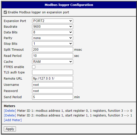
Enable Modbus Logger on the expansion port to turn on the router app. Then configure the connected device by selecting the expansion port and setting the device parameters (Baudrate, Data Bits, Parity, and Stop Bits) from the device datasheet.
Split Timeout — delay between readings; increase it if the connected device cannot meet the requests. Read Period — period between readings to renew the values in the router app buffer.
Cache — selects where the temporary file is stored (e.g., the RAM option stores files in /var/modbus_logger/voldata/). Remote URL — the FTP server address to which files will be sent. Username and Password are used for FTP authentication. Send Period — period between file transfers from the cache to the FTP server.
Meters Configuration
Meter configuration is required, the same as with the Protocol MODBUS-RTUMAP router app.
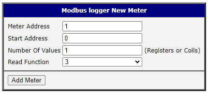
Set Meter Address to 1 unless more Modbus devices are connected to the same serial network.
Start Address is the relative starting address of the coils/registers to be read from the connected serial device. Use this together with Number Of Values, which specifies the number of coils/registers to read from the starting address.
Supported read functions:
1 - Read Coil Status
3 - Read Holding Registers
4 - Read Input Registers
After clicking [Add Meter], the meter appears in the Meters section of the router app.
Example Log File
m0:2023-06-23-13-18-59:01 03 06 00 64 00 c8 01 2c d1 0e
m1:2023-06-23-13-18-59:01 01 02 b5 00 cf 6c
m0:2023-06-23-13-19-09:01 03 06 00 64 00 c8 01 2c d1 0e
m1:2023-06-23-13-19-09:01 01 02 b5 00 cf 6c
m0:2023-06-23-13-19-20:01 03 06 00 64 00 c8 01 2c d1 0e
m1:2023-06-23-13-19-20:01 01 02 b5 00 cf 6cm0— identifier of the user-defined meter.2023-06-23-13-18-59— date and time when the Modbus command was executed (YYYY-MM-DD-hh-mm-ss).- The remainder of the line — the received Modbus command in hexadecimal format.