VLAN
Introduction to VLAN
Tips
The functionality of this Router App is integrated into firmware version 6.5.0 and above. It is not integrated for the v2 product family.
A VLAN (Virtual Local Area Network) uses IP header tagging to simulate multiple LANs within a single physical network. By tagging specific headers to indicate their broadcast domain, VLANs allow you to assign physical or virtual ports to partitioned groups within the existing LAN. This lets you create specialized domains with common topical or geographical attributes, offering flexibility in your network setup.
While each VLAN is distinct—much like separate LANs—multiple VLANs can coexist on the same physical networking segment. However, VLAN-aware networking devices (such as switches, routers, and firewalls) are required to recognize, process, remove, and insert VLAN tags to ensure packets are directed to the correct VLAN.
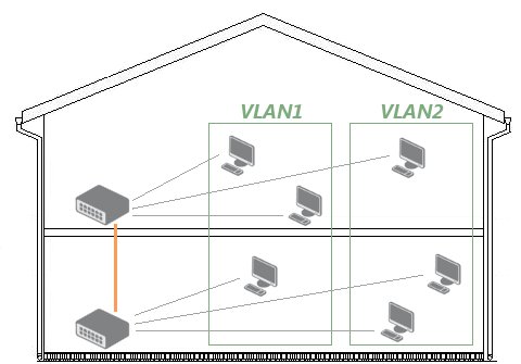
VLAN Example
Imagine a house with two floors, where each floor has three computer stations connected to its own switch. The two switches are connected via a backbone line. To segment the network into two independent groups (VLAN1 and VLAN2), you can create a separate VLAN for each group—since physically creating two separate networks in a two‑floor setup would be complicated.
Configuration
Tips
The following configuration is supported by routers with firmware 3.0.6 and later.
Create VLAN Interface
The following configuration uses the eth1 interface. First, bring the interface up without assigning it an IP address:
ifconfig eth1 0.0.0.0 upNow, create VLAN interfaces for VLAN IDs 11 and 12 on eth1 using the vconfig add command:
vconfig add eth1 11
Added VLAN with VID == 11 to IF -:eth1:-

vconfig add eth1 12
Added VLAN with VID == 12 to IF -:eth1:-
These commands create virtual interfaces eth1.11 and eth1.12. The system treats them as separate network devices, allowing you to configure and assign IP addresses just like any other interface. To verify the creation of the VLAN interfaces, run:
ifconfig -a

eth1.11 Link encap:Ethernet HWaddr 00:30:48:BF:4E:BD
BROADCAST MULTICAST MTU:1500 Metric:1
RX packets:0 errors:0 dropped:0 overruns:0 frame:0
TX packets:0 errors:0 dropped:0 overruns:0 carrier:0
collisions:0 txqueuelen:0
RX bytes:0 (0.0 b) TX bytes:0 (0.0 b)

eth1.12 Link encap:Ethernet HWaddr 00:30:48:BF:4E:BD
BROADCAST MULTICAST MTU:1500 Metric:1
RX packets:0 errors:0 dropped:0 overruns:0 frame:0
TX packets:0 errors:0 dropped:0 overruns:0 carrier:0
collisions:0 txqueuelen:0
RX bytes:0 (0.0 b) TX bytes:0 (0.0 b)
Assign IP Address to the VLAN Interfaces
With the VLAN interfaces created, assign IP addresses using the ifconfig command:
ifconfig eth1.11 192.168.11.254 netmask 255.255.255.0 up
ifconfig eth1.12 192.168.12.254 netmask 255.255.255.0 up
To verify that the IP addresses were assigned successfully, run the ifconfig command for each interface:
ifconfig eth1.11

eth1.11 Link encap:Ethernet HWaddr 00:30:48:BF:4E:BD
inet addr:192.168.11.254 Bcast:192.168.11.255 Mask:255.255.255.0
UP BROADCAST MULTICAST MTU:1500 Metric:1
RX packets:0 errors:0 dropped:0 overruns:0 frame:0
TX packets:0 errors:0 dropped:0 overruns:0 carrier:0
collisions:0 txqueuelen:0
RX bytes:0 (0.0 b) TX bytes:0 (0.0 b)

ifconfig eth1.12

eth1.12 Link encap:Ethernet HWaddr 00:30:48:BF:4E:BD
inet addr:192.168.12.254 Bcast:192.168.12.255 Mask:255.255.255.0
UP BROADCAST MULTICAST MTU:1500 Metric:1
RX packets:0 errors:0 dropped:0 overruns:0 frame:0
TX packets:0 errors:0 dropped:0 overruns:0 carrier:0
collisions:0 txqueuelen:0
RX bytes:0 (0.0 b) TX bytes:0 (0.0 b)