Ignition Sensing Router Setup
Introduction
This application note provides comprehensive guidance for configuring ignition sensing on Advantech routers that have been properly installed and correctly wired.
Ignition sensing enables the router to power on when the vehicle's ignition key is activated and to power off after a preset time delay once the ignition key is deactivated.
Operating Principle
A router connected to a vehicle in this manner must support Low Power Mode (LPM) and have a Digital Input (DI). The router remains continuously connected to the power supply in sleep mode until it is awakened by a signal to the DI when the vehicle’s ignition starts.
When the vehicle is turned off, the router shuts down after a configurable delay. This delay is set in the Router App Sleep Mode, which must be installed on the router. Within this app, you enable the router to wake from sleep mode via the digital input signal and specify how long the router stays powered on after the vehicle is turned off.
Product Families Setup
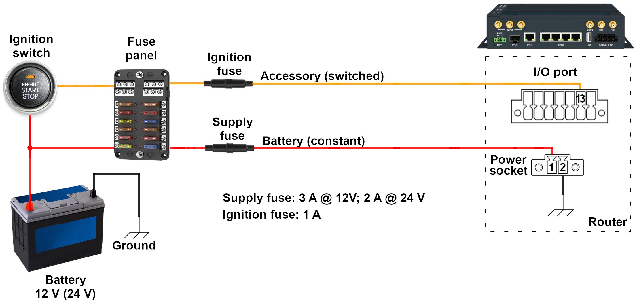
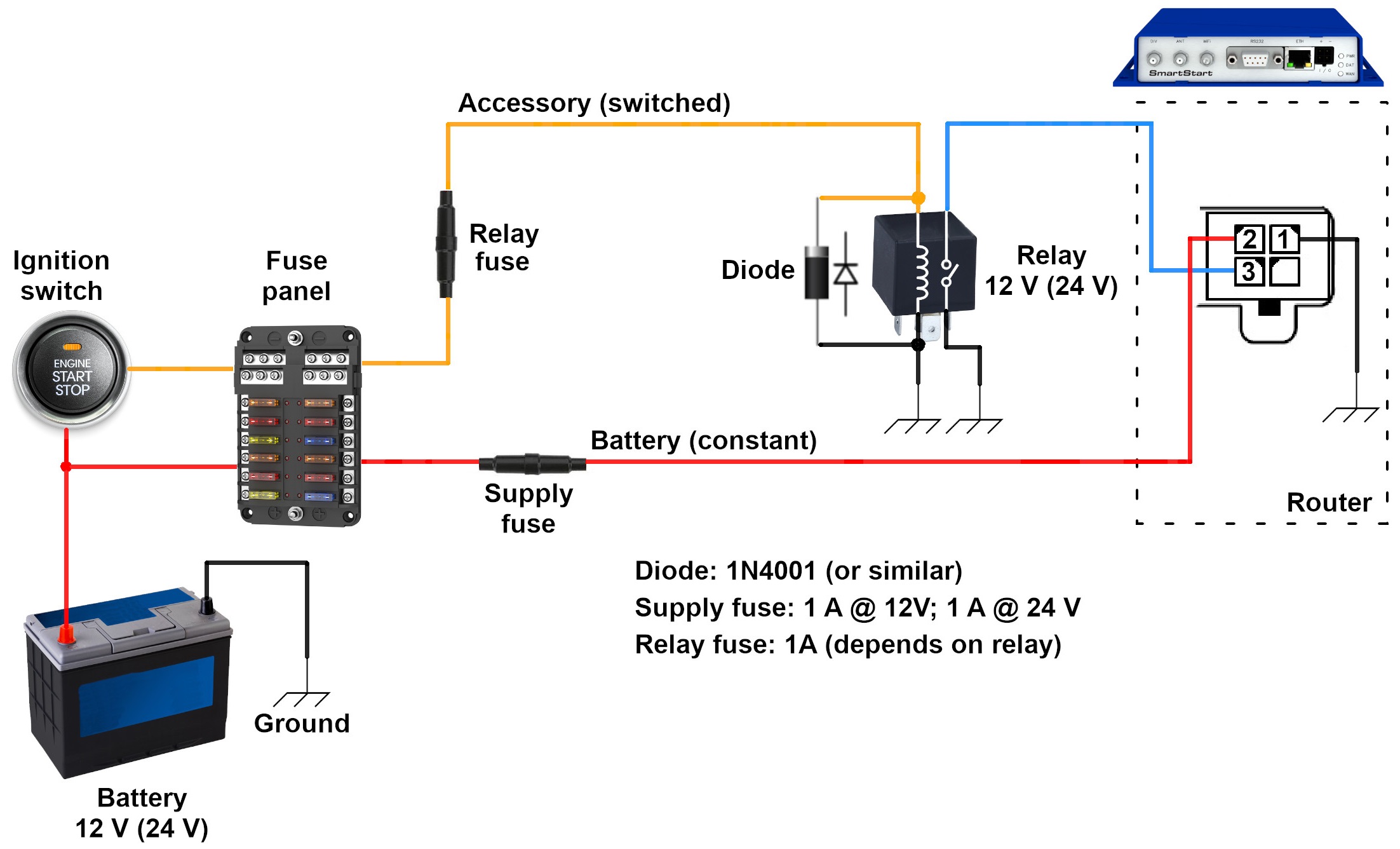
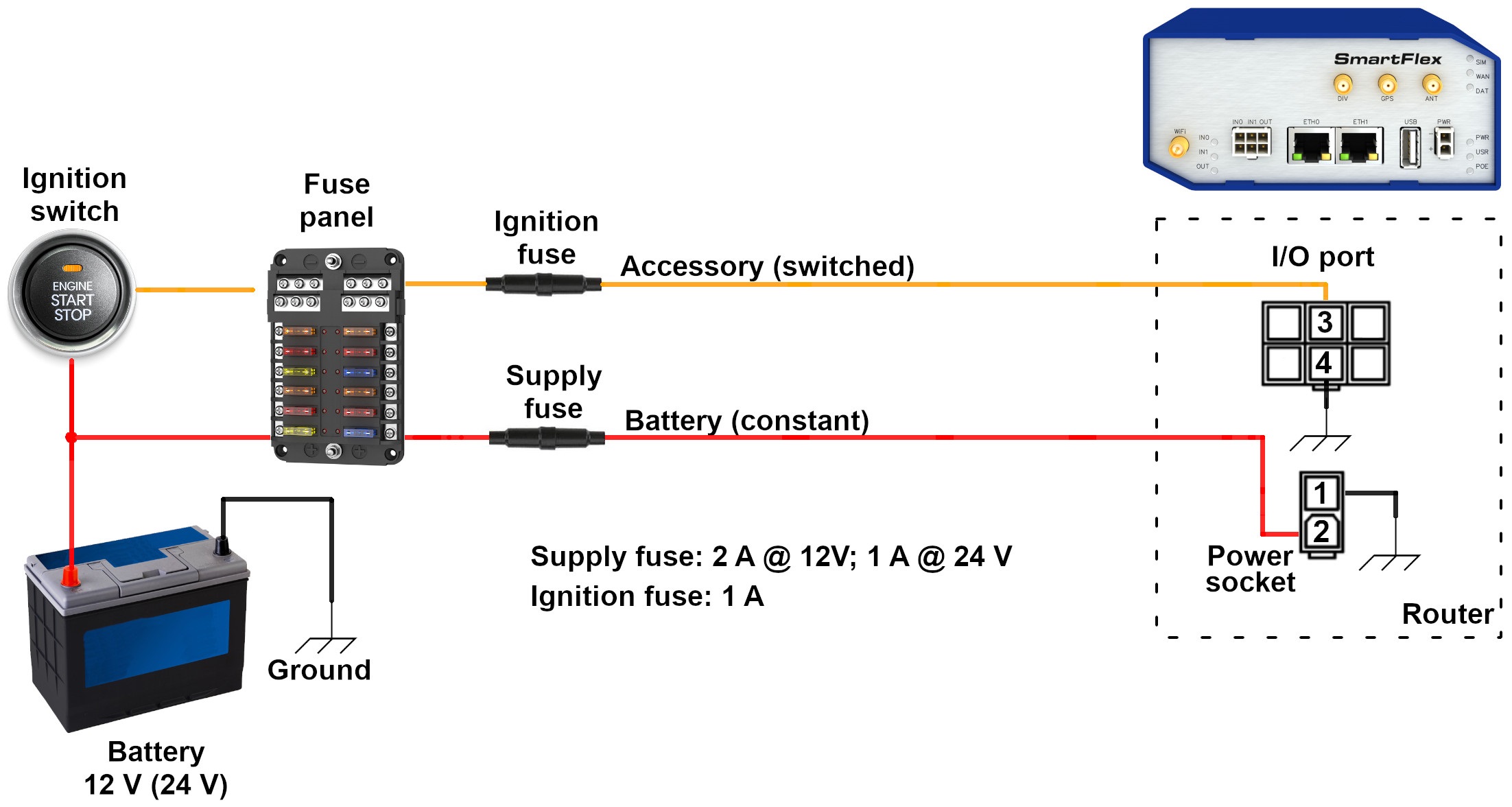
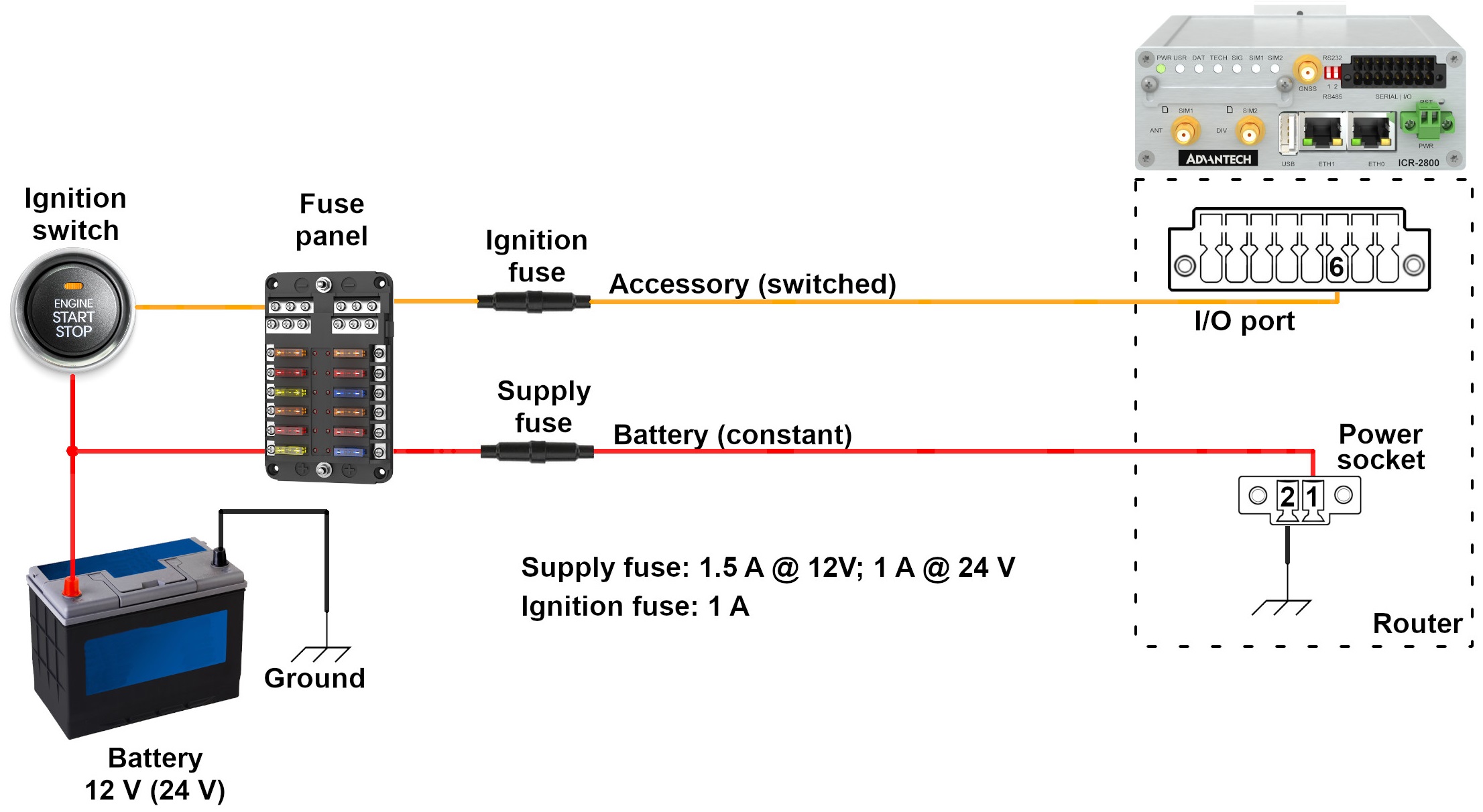
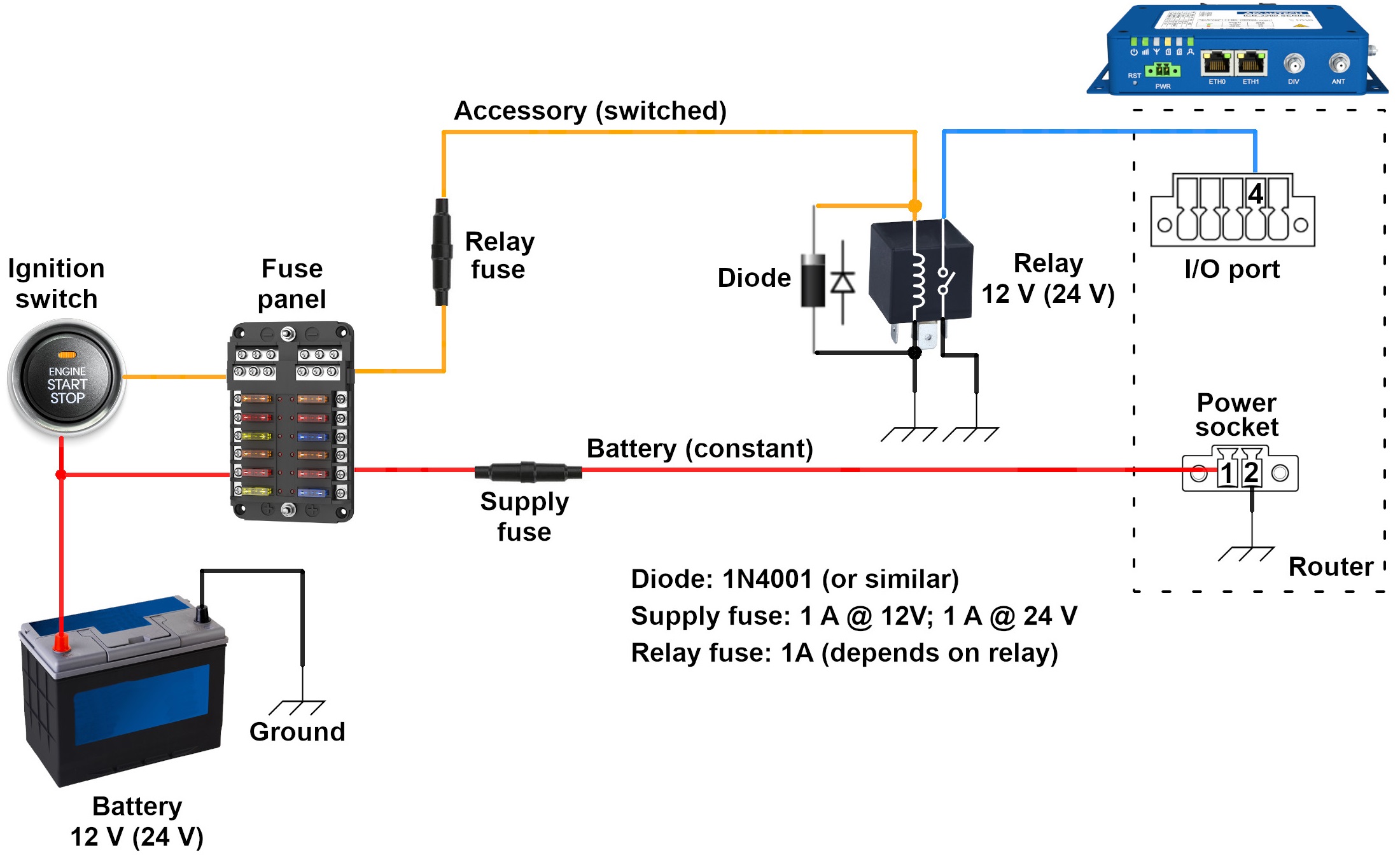
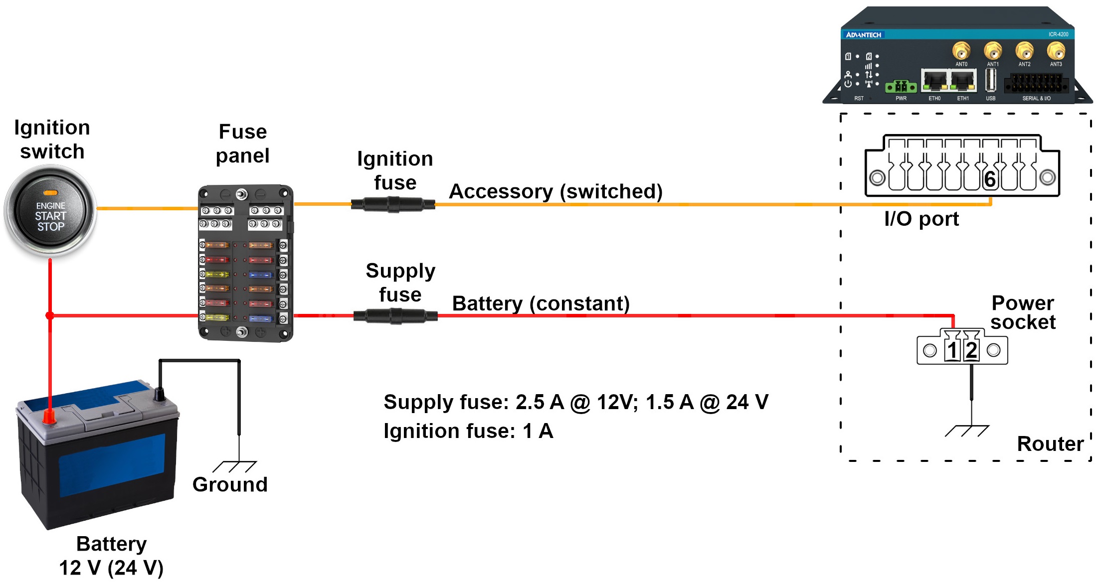
This chapter is organized into subchapters, each focusing on a distinct router family. In each subchapter, the first figure presents a functional diagram depicting the router's connection to a vehicle, illustrating the necessary wiring and components for successful integration. The second figure details the required configuration for the Sleep Mode Router App.
Connection Setup
Tips
For details about router connections, parameters, and more, refer to the manual page for your router model. Similarly, information about the router’s power consumption in sleep mode can be found in the manual under the section Technical Parameters → Basic Parameters.
Advantech routers offer two primary connection methodologies, determined by their internal circuit design: with or without a relay. When a router family requires the use of a relay, it is imperative to select the appropriate relay type—either 12 V or 24 V coil voltage—according to the vehicle’s electrical system. A diode is typically connected in parallel to the relay coil to protect the control circuit from sudden voltage spikes. If the relay includes a built-in flyback diode, an additional external diode is not required. However, omitting this diode when it is not integrated into the relay could potentially damage the device.
For circuit protection, it is advisable to use the correct fuses; class T fuses are recommended for this application.
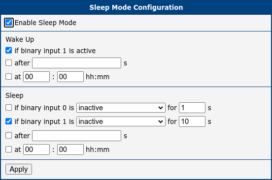
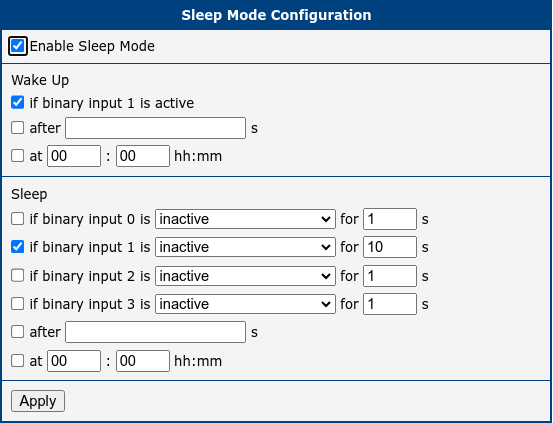
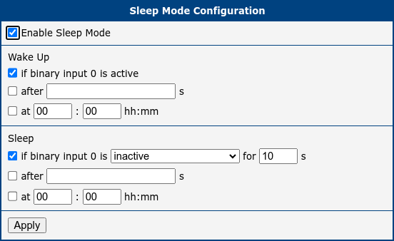
Sleep Mode Router App Configuration
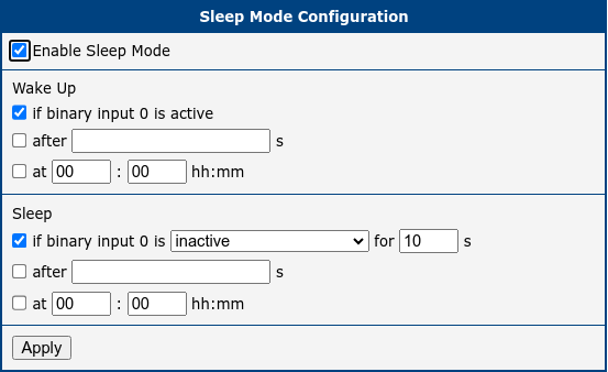
The second figure in each subchapter illustrates the setup of the Sleep Mode Router App, which is essential for system functionality. To engage Low Power Mode (LPM), check the Enable Sleep Mode option. Set the Wake Up feature to activate the router upon detecting an active digital input. Additionally, specify how long the router should wait before returning to sleep mode after the vehicle’s ignition is switched off by adjusting the Sleep if digital input is inactive for x s setting. Although the default setting in these examples is 10 seconds, this interval can be modified to suit your requirements.
Warning
In case of incorrect wiring (if the relevant BIN is inactive), the router enters sleep mode after the configured delay—either when the configuration is confirmed with the Apply button or upon connecting the router to the power supply. The router is inaccessible in sleep mode!
SmartStart (BB-SLxx) Family
SmartFlex (BB-SRxx) Family
ICR-2800 Family
ICR-3200 Family
ICR-4200 Family

ICR-4400 Family