Expansion Port Mounting
Safety Instruction
Caution
Observe the following instructions:
- The expansion port must be used in compliance with all applicable international and national laws and in compliance with any special restrictions regulating the use of the communication module in prescribed applications and environments.
- Use only the original Advantech Czech company accessories. This prevents possible health risks and damage to the devices and ensures compliance with all relevant provisions. Unauthorized adjustments or use of unapproved accessories may result in damage to the expansion port and breach of applicable laws. Use of unapproved adjustments or accessories may lead to the cancellation of the guarantee, which has no effect on your legal rights.
- Do not expose the expansion port to extreme conditions. Protect it from dust, moisture, and heat.
Product Disposal Instructions
The WEEE (Waste Electrical and Electronic Equipment: 2012/19/EU) directive has been introduced to ensure that electrical/electronic products are recycled using the best available recovery techniques to minimize the environmental impact.
This product contains high-quality materials and components that can be recycled. At the end of its life, this product MUST NOT be mixed with other commercial waste for disposal. Check the terms and conditions of your supplier for disposal information.
Plastic Enclosure
Caution
Expansion port PORT1 and PORT2 can be connected only when the router is switched off.
First, remove (snap out) the front panel (position 5) and then take out the B-RB-v2 motherboard (position 1). Connect the expansion port PORT1 (position 2) to connector J8 (see the figure below) of the router motherboard (B-RB-v2, position 1) from the TOP side. Connect the expansion port PORT2 (position 3) to connector J3 (see the figure below) of the router motherboard (B-RB-v2, position 1) from the TOP side. Attach each expansion port to the B-RB-v2 board using three spacers (position 10). After mounting the expansion port, slide the router (motherboard with expansion ports) into the box and snap the front panel in.
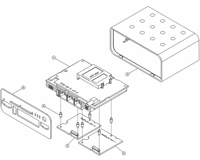
| Part | Description | Count |
|---|---|---|
| 1 | Router motherboard | 1 |
| 2 | Expansion port PORT 1 | 1 |
| 3 | Expansion port PORT 2 | 1 |
| 4 | Router box | 1 |
| 5 | Front panel of the router | 1 |
| 6 | Spacers for attaching the expansion port to the motherboard | 6 |
Part list for routers in plastic enclosure
Metal Enclosure
Caution
Expansion port PORT1 and PORT2 can be connected only when the router is switched off.
Unscrew four screws (position 11) on the rear panel (position 6) and remove it. Then take out the B-RB-v2 motherboard (position 1). Connect the expansion port PORT1 (position 2) to connector J8 (see the figure below) of the router motherboard (B-RB-v2, position 1) from the TOP side. Connect the expansion port PORT2 (position 3) to connector J3 (see the figure below) of the router motherboard (B-RB-v2, position 1) from the TOP side. Attach each expansion port to the B-RB-v2 board using three spacers (position 10). After mounting the expansion port, slide the router (motherboard with expansion ports) into the enclosure, place the rear panel on the enclosure, and secure it with four screws (position 11).
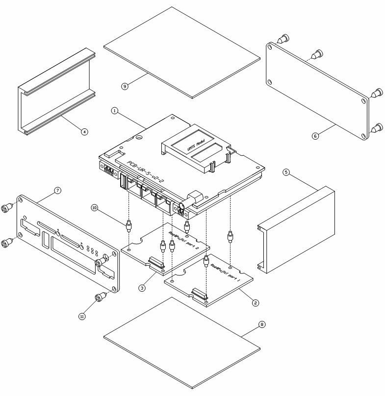
| Part | Description | Count |
|---|---|---|
| 1 | Router motherboard | 1 |
| 2 | Expansion port PORT 1 | 1 |
| 3 | Expansion port PORT 2 | 1 |
| 4 | Left sidewall | 1 |
| 5 | Right sidewall | 1 |
| 6 | Rear panel of the router | 1 |
| 7 | Front panel of the router | 1 |
| 8 | Bottom cover | 1 |
| 9 | Top cover | 1 |
| 10 | Spacers for attaching the expansion port to the motherboard | 6 |
| 11 | Screws for assembling the router enclosure | 8 |
Part list for routers in metal enclosure