DNP3 Outstation
Caution
- This Router App was tested on firmware version 6.3.10. If you update the router firmware, check whether a compatible version of this Router App has also been released and update it accordingly for compatibility.
- This manual is intended for the version of the Router App that is not compatible with the v2 router platform.
The DNP3 Outstation Router App enables the router to communicate using the DNP3 (Distributed Network Protocol v.3) protocol. The app provides two main functionalities:
- DNP3 Outstation: The router acts as an outstation (or slave device), collecting data from its own inputs (e.g., digital inputs, voltage, temperature) and system variables. It reports this data to a DNP3 master, which is typically a SCADA server.
- DNP3 Gateway: The router can also function as a gateway, routing DNP3 messages between the IP-based master and other DNP3 devices connected to the router's serial ports.
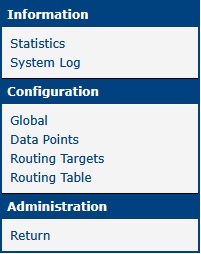
The DNP3 Outstation Router App has a web interface for configuration, which can be accessed by clicking the app's name on the Router Apps page of the main router web interface. The left pane of the web interface contains a menu for configuring and monitoring the app. It includes sections for Information, Configuration, and Administration. The Administration section contains the Return link, which takes you back to the main router web interface.
Configuration
Caution
If you are logged in with the Usr role, you will have read-only access to all configuration pages.
The DNP3 Outstation app is configured using the Global, Data Points, Routing Targets, and Routing Table pages, located in the Configuration section of the app's web interface.
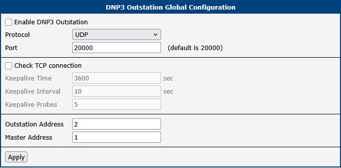
Global
The Global page contains settings for the primary UDP/TCP connection and for verifying an established TCP connection. The Enable DNP3 Outstation checkbox activates the app. The other settings are described below.
| Item | Description |
|---|---|
| Protocol | Selects the communication protocol. • TCP: The connection-oriented TCP protocol. • UDP: The connectionless UDP protocol. |
| Port | Specifies the port on which the router will listen for connections (default: 20000). |
Connection configuration
Selecting the Check TCP connection checkbox enables keepalive probes to verify that an established TCP connection is still active. The following parameters can be configured:
| Item | Description |
|---|---|
| Keepalive Time | The idle time in seconds before sending the first keepalive probe (default: 3600). |
| Keepalive Interval | The time in seconds to wait for a response to a keepalive probe (default: 10). |
| Keepalive Probes | The number of unacknowledged probes to send before considering the connection dropped (default: 5). |
TCP connection check
Specify the master and outstation device addresses:
| Item | Description |
|---|---|
| Outstation Address | The DNP3 address of this router (the outstation). |
| Master Address | The DNP3 address of the master device that will connect to this outstation. |
Device specification
Data Points
The Data Points page is used to configure which data points are enabled and how they are reported.
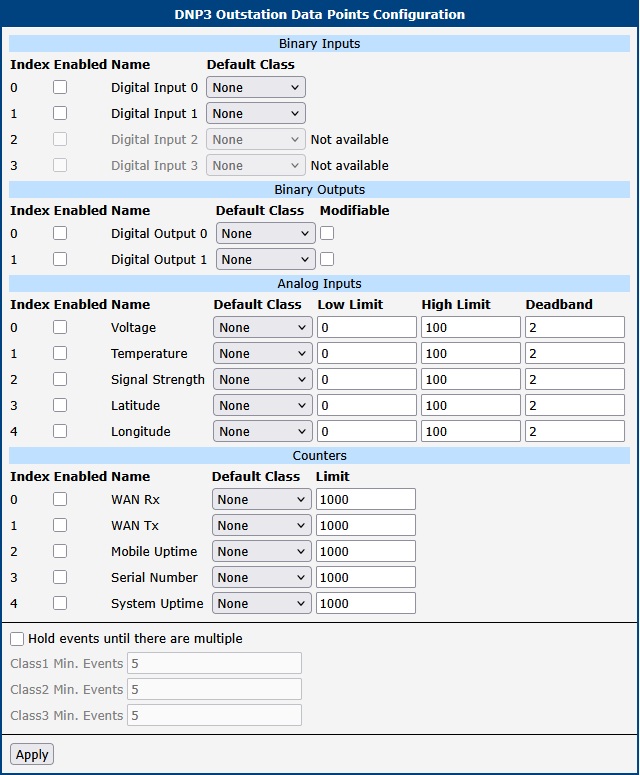
Data points are enabled using the checkbox in the Enabled column. In the Default Class column, you can assign a class to each data point. This class determines how event data is reported.
The following subsections describe the available data points, grouped by type.
Digital Inputs
| Index | Description |
|---|---|
| 0 | Digital Input 0 — The first digital input |
| 1 | Digital Input 1 — The second digital input |
| 2 | Digital Input 2 — The third digital input |
| 3 | Digital Input 3 — The fourth digital input |
Digital Outputs
| Index | Description |
|---|---|
| 0 | Digital Output 0 — The first digital output |
| 1 | Digital Output 1 — The second digital output |
When the Modifiable column is checked, you can change the value of the digital output using a control command (select-operate or direct-operate). Only CROB LATCH variation is supported.
Analog Inputs
For Analog Inputs, you can also configure Low Limit, High Limit, and Deadband values for event generation. Low Limit and High Limit define the thresholds for the analog value. The Deadband value prevents multiple events from being generated when an analog value fluctuates near a limit. After a limit is crossed, the value must return past the limit by the deadband amount before it is considered to have returned to the normal range.
For example, if Low Limit is 10 and Deadband is 2, an event is triggered when the value drops below 10. The value is considered back to normal only after it rises above 12 (Low Limit + Deadband). Similarly, if High Limit is 50, an event is triggered when the value exceeds 50, and it returns to normal only after dropping below 48 (High Limit − Deadband).
| Index | Description |
|---|---|
| 0 | Input supply voltage. The value must be divided by 1000 to get the voltage in Volts. |
| 1 | Internal router temperature in degrees Celsius (°C). |
| 2 | Signal strength of the cellular connection. |
| 3 | GPS Latitude in degrees. The value must be divided by 1,000,000. |
| 4 | GPS Longitude in degrees. The value must be divided by 1,000,000. |
Caution
- The ability to read input voltage and router temperature is not available on all router models.
- GPS values are only available on routers with GNSS hardware. The GPS Router App must also be installed and running on these devices.
Counters
| Index | Description |
|---|---|
| 0 | Received data on the primary WAN interface (in bytes). |
| 1 | Transmitted data on the primary WAN interface (in bytes). |
| 2 | Duration of the current mobile WAN connection (in minutes). |
| 3 | Serial number cut to only the last nine digits. |
| 4 | Total system uptime since the last reboot (in seconds). |
The Limit column specifies how much a counter value must increase before an event is sent.
Number of Events
The settings at the bottom of the page let you control when unsolicited event messages are sent. If the Hold events until there are multiple checkbox is unchecked, messages are sent immediately. If the checkbox is checked, messages are held until the queue for a given class reaches the number specified by ClassX Min. Events. Setting this value to 1 also causes messages to be sent immediately.
Routing Targets
The Routing Targets page is used to define communication endpoints (targets) for routing DNP3 messages. These targets can be local serial ports or remote IP connections. If the router has a serial expansion port, a section for configuring it will be displayed. This section is hidden if no serial port is available.
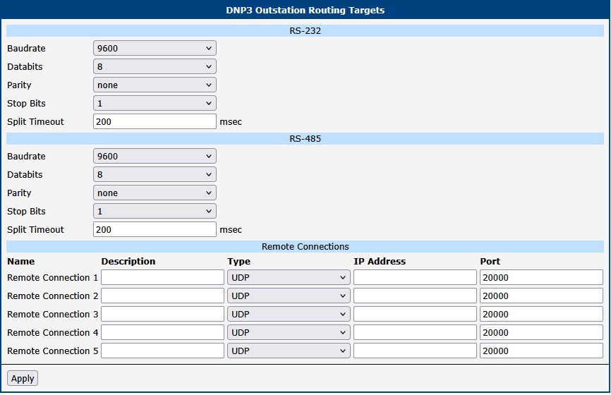
Configure the following serial port parameters:
| Item | Description |
|---|---|
| Baudrate | Serial communication speed in bits per second (bps). |
| Databits | The number of data bits per character. |
| Parity | Parity bit for error checking. • none: No parity bit is used. • even: Even parity is used. • odd: Odd parity is used. |
| Stop Bits | The number of stop bits to indicate the end of a character. |
| Split Timeout | The timeout in milliseconds for assembling message fragments. If a pause between received characters on the serial line exceeds this value, the router assumes the message is complete and processes the received data. |
Expansion port configuration
The Remote Connections section allows you to define network targets. These defined targets are available for selection in the DNP3 routing table.
| Item | Description |
|---|---|
| Description | A user-friendly name or description for the remote connection. |
| Type | The network protocol to use for the connection. • TCP: The connection-oriented TCP protocol. • UDP: The connectionless UDP protocol. |
| IP Address | The IP address of the remote DNP3 device. |
| Port | The TCP or UDP port number of the remote DNP3 device. |
Remote connections configuration
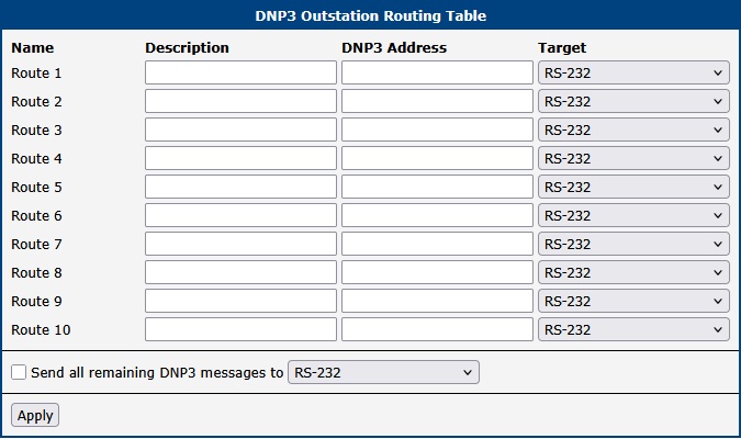
Routing Table
The Routing Table page allows you to create static routes for DNP3 messages. Each rule maps a destination DNP3 Address to a specific communication Target that was configured on the Routing Targets page. When the router receives a message for a specific DNP3 address, it forwards it to the corresponding target.
The individual columns have the following meaning:
| Item | Description |
|---|---|
| Name | The name of the route (e.g., Route 1). |
| Description | An optional description for the route. |
| DNP3 Address | The destination DNP3 address for this route. |
| Target | The communication endpoint for this route. The dropdown list contains all serial ports and remote connections defined on the Routing Targets page. |
Routing table configuration
The Send all remaining DNP3 messages to option defines a default route. Any message for a DNP3 address not explicitly defined in the routing table will be sent to this selected target.
Application Activity Monitoring
Statistics
To view communication statistics, navigate to Information → Statistics in the app's web interface. This page displays low-level statistics, including the number of frames sent and received, and the count of CRC errors.
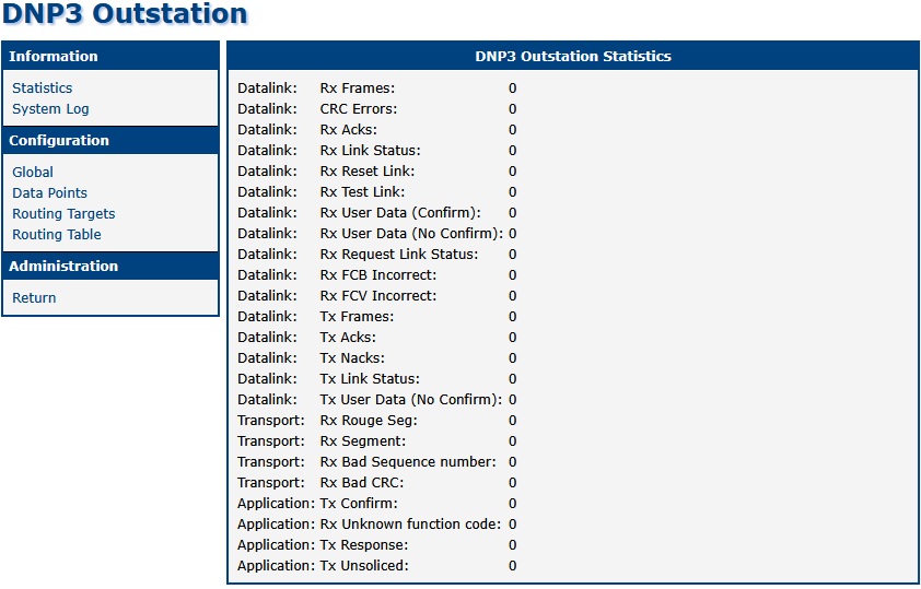
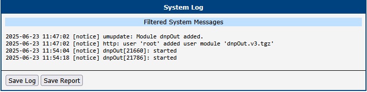
System Log
For troubleshooting, you can view detailed log messages by navigating to Information → System Log within the app's interface. This log is filtered to show only messages from the DNP3 Outstation app. To view the complete, unfiltered system log, navigate to Status → System Log in the main router web interface.