Modbus Logger
Tips
For an overview of the Modbus protocol, communication modes, and how to connect Modbus devices to Advantech routers, see the Modbus Application Guide.
Module Usage
Description
Tips
This Router App is not compatible with the v4 router platform.
The Modbus Logger Router App can be used for logging communication from a Modbus RTU device connected to the serial interface of an Advantech router. RS232 or RS485/422 serial interfaces can be used for this purpose. The serial interface is available as an expansion port on some routers or may be built in on certain models.
A meter is a configuration of address, data length, and read function for Modbus data capturing. Any number of meters can be defined for data logging. Data from all meters are consolidated in a configured storage location and then periodically sent to an FTP(S) server at defined intervals.
Web Interface
Once the installation is complete, the Router App's web interface can be accessed by clicking the Router App name on the Router Apps page of the router's web interface.
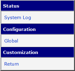
The left part of the web interface contains a menu with a Status section, followed by a Configuration section containing the Global configuration page. The Customization section contains only the Return item, which switches back to the router's web configuration pages. The main menu is shown in the figure below.
Configuration
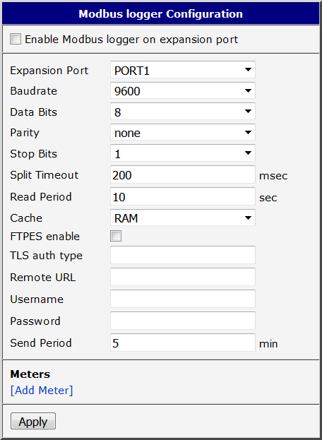
Configure the Router App on the Global page under the Configuration menu section. The form contains three main parts: serial line parameters, FTP(S) server connection settings, and meter definitions. Meter configuration is described in detail in the section below.
| Item | Description |
|---|---|
| Enable Modbus Logger on Expansion Port | If enabled, the logging functionality of the module is turned on. |
| Expansion Port | Choose the expansion port (port1 or port2) with a serial interface for Modbus data logging. Port 1 corresponds to the ttyS0 device, port 2 to ttyS1. |
| Baudrate | Choose the baudrate for Modbus communication. |
| Data Bits | Choose the data bits for Modbus communication. |
| Parity | Choose the parity for Modbus communication. |
| Stop Bits | Choose the stop bits for Modbus communication. |
| Split Timeout | Maximum time interval allowed between two received bytes. If exceeded, the data is treated as invalid. |
| Read Period | Time period for capturing data from the Modbus device. Minimum value is 5 seconds. |
| Cache | Select the destination for module data storage. Logged data is stored here as files and deleted once successfully sent to the server. Options: • RAM — store in RAM memory • SDC — store on SD card • USB — store on USB disk |
| FTPES Enable | Enables FTPES — FTP with Transport Layer Security (TLS) support. The remote URL starts with ftp://. |
| TLS Auth Type | Specifies the TLS authentication type (parameter for the curl program). Currently, only TLS-SRP is supported. Enter the string: -tlsauthtype=SRP. |
| Remote URL | Remote URL of the directory on the FTP(S) server for data storage. The address must end with a slash (/). |
| Username | Username for access to the FTP(S) server. |
| Password | Password for access to the FTP(S) server. |
| Send Period | Time interval at which data captured locally on the router is uploaded to the FTP(S) server. Minimum value is 5 minutes. |
| Meters | Definition of meters. For more information see the Meters Configuration section below. |
| Apply | Button to save and apply all changes made in this configuration form. |
Configuration items
Meters Configuration
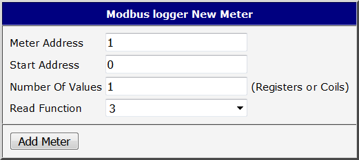
A meter is a configuration of address, data length, and read function for Modbus data capturing. A new meter can be added by clicking the [Add Meter] link in the Meters section of the configuration page. To delete an existing meter, click the [Delete] button on the main configuration screen.
| Item | Description |
|---|---|
| Meter Address | Address of the slave device (1 to 247). |
| Start Address | Start reference of the registers/coils address. |
| Number of Values | Number of register/coil values to be captured. |
| Read Function | Read function code: 1 = Read Coils 3 = Read Holding Registers 4 = Read Input Registers |
| Add Meter | Button to save the new meter configuration. |
Meter configuration items
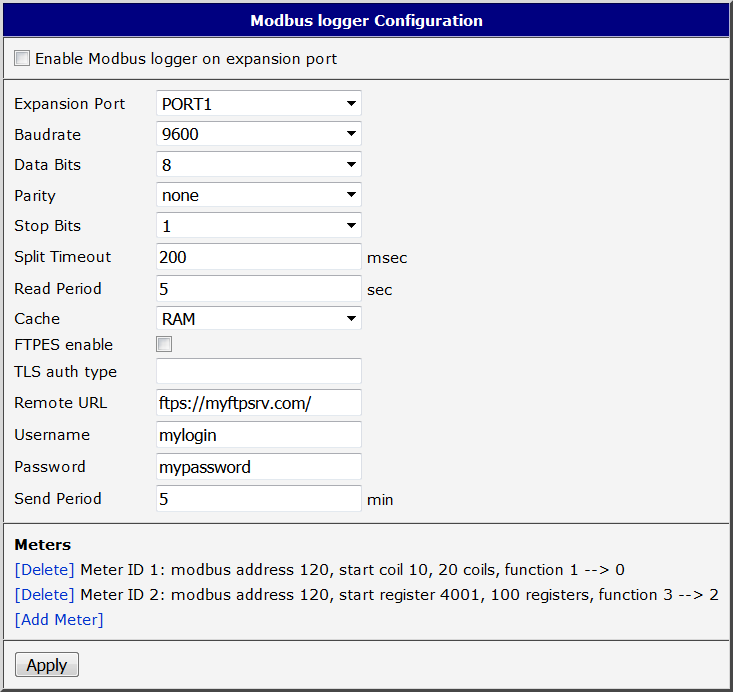
Configuration Example
In the example below, data is captured from a Modbus RTU device connected to the first serial interface every 5 seconds. Data is read from a Modbus slave device with address 120, and two meters are defined. The first meter reads 10 coil values starting at coil 10. The second meter reads 100 registers starting at register 4001.
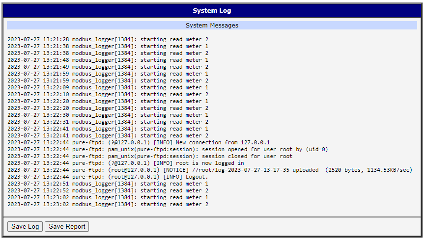
System Log
Log messages are available on the System Log page under the Status menu section. This log contains messages from this Router App as well as all other router system messages, and is identical to the system log available in the router's main Status → System Log page.
Log File Contents
The Modbus Logger generates log files to record communication data from the Modbus RTU device. Each log file is named using the format log-YYYY-MM-dd-hh-mm-ss, where the components represent the year, month, day, hour, minute, and second of the execution time.
Each line in the log file follows this structure:
m0:2023-06-23-13-14-03:01 03 06 00 64 00 c8 01 2c d1 0em0— the identifier of the user-defined meter.2023-06-23-13-14-03— the date and time when the Modbus command was executed, inYYYY-MM-dd-hh-mm-ssformat.- The remainder of the line represents the received Modbus command in hexadecimal format.
Each line in the log file corresponds to one executed Modbus command and follows the same structure as shown above.