Protocol MODBUS-TCP2RTU
Caution
- This Router App has been tested on a router with firmware version 6.3.10. After updating the router firmware to a higher version, check whether a newer version of the Router App has also been released and update it accordingly for compatibility.
Description
The Modbus TCP2RTU Router App provides conversion of the MODBUS TCP protocol to the MODBUS RTU protocol for use on a serial line. RS-232 or RS-485/422 interfaces can be used for serial communication in the Advantech router.
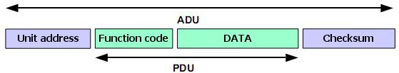
Both protocols share a common part — the Protocol Data Unit (PDU). An MBAP header is used for identification when sending a MODBUS ADU over TCP/IP. Port 502 is reserved for MODBUS TCP ADU.
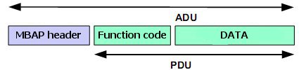
When sending a PDU to the serial line, the destination unit address (obtained from the MBAP header as the Unit ID) is prepended to the PDU along with a checksum.
The Router App supports configuration of two independent serial interfaces, if available in the router. Automatic recognition of RS-485 vs. RS-422 is supported.
Web Interface
The web interface is accessible by clicking the Router App name on the Router Apps page of the router's web interface.
The left menu contains three sections: Status (with Stats for statistical information and System Log), Configuration (with Port 1, Port 2, and USB items), and Customization (with only Return, which switches back to the router's main web interface).

Configuration
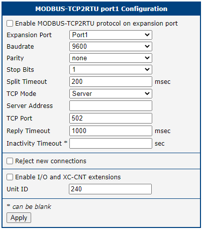
Port Configuration
| Item | Description |
|---|---|
| Enable | Enables conversion of MODBUS TCP/IP protocol to MODBUS RTU. |
| Expansion port | Expansion port on which the MODBUS RTU connection is established. If no MODBUS RTU device is connected to the serial interface, this can be set to "None", allowing the serial interface to be used for another purpose. In this case, only internal registers of the router can be read. See the Address Space of Router section for details. |
| Baudrate | Applied communication speed. |
| Parity | Control parity bit: • none — No parity. • even — Even parity. • odd — Odd parity. |
| Stop Bits | Number of stop bits. |
| Split Timeout | Time for delimiting a message (see note below). |
| TCP Mode | Selection of operating mode: • Server — TCP server mode. • Client — TCP client mode. |
| Server Address | Server address when Client is selected in TCP Mode. |
| TCP Port | TCP port on which the router listens for MODBUS TCP connection requests. Port 502 is reserved for MODBUS ADU. |
| Reply Timeout | Time interval in which a response is expected. If no response is received, one of the following error codes is sent: • 0A — Transmission path unavailable: the gateway cannot allocate an internal path from the input to the output port (likely overloaded or misconfigured). • 0B — Target device not responding: the device may be unavailable. |
| Inactivity Timeout | Time period after which the TCP/UDP connection is terminated due to inactivity. |
| Reject new connections | When enabled, the router rejects any additional connection attempts and no longer supports multiple simultaneous connections. |
| Enable I/O and XC-CNT extensions | Enables direct communication with the router. I/O (binary inputs and outputs on the router) and internal registers work on all platforms (v2, v2i, v3, and v4). XC-CNT is an expansion board for v2 routers. This form of communication is supported on the v2 platform only. |
| Unit ID | ID for direct communication with the router. Range: 1 to 255. Value 0 is also accepted for communication with MODBUS/TCP or MODBUS/UDP devices. Default: 240. |
Port configuration items
Click Apply to apply all configuration changes.
Tips
If the gap between two received characters exceeds the Split Timeout value (in milliseconds), a message is assembled from all received data and sent.
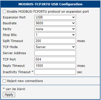
USB Configuration
Tips
USB configuration is only available on products equipped with a USB port.
The USB configuration form contains nearly the same items as PORT 1 and PORT 2. The only difference is that the Enable I/O and XC-CNT extensions and Unit ID items are not available.
I/O & XC-CNT MODBUS TCP Server
Basic Characteristic
The I/O protocol and XC-CNT MODBUS TCP server implement direct router communication via the Modbus TCP2RTU Router App, based on the I/O interface and XC-CNT expansion boards. The router provides the current state of inputs in real time. The system reads this state using message code 0x03 (read multiple registers). Using message code 0x10 (write multiple registers), the system can control digital outputs and set counter states. Messages with other codes (e.g., 0x06 for writing a single register) are not supported.
Address Space of Router
Tips
Addresses in the tables start from 0. If the implementation uses register numbers starting from 1, the register address must be incremented by 1.
| Address | Access | Description |
|---|---|---|
| 0x0400 | R/- | upper 16 bits of temperature in router [°C] (with sign) |
| 0x0401 | R/- | upper 16 bits of temperature in router [°C] (with sign) |
| 0x0402 | R/- | upper 16 bits of the supply voltage [mV] |
| 0x0403 | R/- | upper 16 bits of the supply voltage [mV] |
| 0x0404 | R/- | state of upper 16 bits of BIN2, always 0 |
| 0x0405 | R/- | state of lower 16 bits of BIN2 |
| 0x0406 | R/- | state of upper 16 bits of BIN3, always 0 |
| 0x0407 | R/- | state of lower 16 bits of BIN3 |
| 0x0408 | R/- | state of upper 16 bits of BIN0, always 0 |
| 0x0409 | R/- | state of lower 16 bits of BIN0: • bit 0 — level at the input BIN0 • bits 1 to 15 — not used, always 0 |
| 0x040A | R/- | state of upper 16 bits of BOUT0, always 0 |
| 0x040B | R/W | state of lower 16 bits of BOUT0: • bit 0 — level at the output BOUT0 • bits 1 to 15 — not used, always 0 |
| 0x040C | R/- | state of upper 16 bits of BIN1, always 0 |
| 0x040D | R/- | state of lower 16 bits of BIN1: • bit 0 — level at the input BIN1 • bits 1 to 15 — not used, always 0 |
| 0x040E | R/- | state of upper 16 bits of BOUT1, always 0 |
| 0x040F | R/W | state of lower 16 bits of BOUT1: • bit 0 — level at the output BOUT1 • bits 1 to 15 — not used, always 0 |
I/O
| Address | Access | Description |
|---|---|---|
| 0x0410 | R/- | upper 16 bits of AN1 value, always 0 |
| 0x0411 | R/- | lower 16 bits of AN1 value, value from 12-bit A-D converter |
| 0x0412 | R/- | upper 16 bits of AN2 value, always 0 |
| 0x0413 | R/- | lower 16 bits of AN2 value, value from 12-bit A-D converter |
| 0x0414 | R/W | upper 16 bits of CNT1 |
| 0x0415 | R/W | lower 16 bits of CNT1 |
| 0x0416 | R/W | upper 16 bits of CNT2 |
| 0x0417 | R/W | lower 16 bits of CNT2 |
| 0x0418 | R/- | state of upper 16 binary inputs: • bits 0 to 15 — not used, always 0 |
| 0x0419 | R/- | state of lower 16 binary inputs: • bit 0 — level at the input BIN1 • bit 1 — level at the input BIN2 • bit 2 — level at the input BIN3 • bit 3 — level at the input BIN4 • bits 4 to 15 — not used, always 0 |
| 0x041A | R/- | state of upper 16 binary outputs: • bits 0 to 15 — not used, always 0 |
| 0x041B | R/W | state of lower 16 binary outputs: • bit 0 — level at the output BOUT1 • bits 1 to 15 — not used, always 0 |
| 0x041C | R/- | not used, always 0 |
| 0x041D | R/- | not used, always 0 |
| 0x041E | R/- | not used, always 0 |
| 0x041F | R/- | not used, always 0 |
XC-CNT — PORT1
| Address | Access | Description |
|---|---|---|
| 0x0420 | R/- | upper 16 bits of AN1 value, always 0 |
| 0x0421 | R/- | lower 16 bits of AN1 value, value from 12-bit A-D converter |
| 0x0422 | R/- | upper 16 bits of AN2 value, always 0 |
| 0x0423 | R/- | lower 16 bits of AN2 value, value from 12-bit A-D converter |
| 0x0424 | R/W | upper 16 bits of CNT1 |
| 0x0425 | R/W | lower 16 bits of CNT1 |
| 0x0426 | R/W | upper 16 bits of CNT2 |
| 0x0427 | R/W | lower 16 bits of CNT2 |
| 0x0428 | R/- | state of upper 16 binary inputs: • bits 0 to 15 — not used, always 0 |
| 0x0429 | R/- | state of lower 16 binary inputs: • bit 0 — level at the input BIN1 • bit 1 — level at the input BIN2 • bit 2 — level at the input BIN3 • bit 3 — level at the input BIN4 • bits 4 to 15 — not used, always 0 |
| 0x042A | R/- | state of upper 16 binary outputs: • bits 0 to 15 — not used, always 0 |
| 0x042B | R/W | state of lower 16 binary outputs: • bit 0 — level at the output BOUT1 • bits 1 to 15 — not used, always 0 |
| 0x042C | R/- | not used, always 0 |
| 0x042D | R/- | not used, always 0 |
| 0x042E | R/- | not used, always 0 |
| 0x042F | R/- | not used, always 0 |
XC-CNT — PORT2
| Address | Access | Description |
|---|---|---|
| 0x0430 | R/- | upper 16 bits of serial number |
| 0x0431 | R/- | lower 16 bits of serial number |
| 0x0432 | R/- | 1st and 2nd byte of MAC address |
| 0x0433 | R/- | 3rd and 4th byte of MAC address |
| 0x0434 | R/- | 5th and 6th byte of MAC address |
| 0x0435 | R/- | 1st and 2nd byte of IP address MWAN |
| 0x0436 | R/- | 3rd and 4th byte of IP address MWAN |
| 0x0437 | R/- | number of active SIM |
| 0x0438 | R/- | 1st and 2nd byte of MWAN Rx Data |
| 0x0439 | R/- | 3rd and 4th byte of MWAN Rx Data |
| 0x043A | R/- | 5th and 6th byte of MWAN Rx Data |
| 0x043B | R/- | 7th and 8th byte of MWAN Rx Data |
| 0x043C | R/- | 1st and 2nd byte of MWAN Tx Data |
| 0x043D | R/- | 3rd and 4th byte of MWAN Tx Data |
| 0x043E | R/- | 5th and 6th byte of MWAN Tx Data |
| 0x043F | R/- | 7th and 8th byte of MWAN Tx Data |
| 0x0440 | R/- | 1st and 2nd byte of MWAN Uptime |
| 0x0441 | R/- | 3rd and 4th byte of MWAN Uptime |
| 0x0442 | R/- | 5th and 6th byte of MWAN Uptime |
| 0x0443 | R/- | 7th and 8th byte of MWAN Uptime |
| 0x0444 | R/- | MWAN Registration |
| 0x0445 | R/- | MWAN Technology |
| 0x0446 | R/- | MWAN PLMN |
| 0x0447 | R/- | MWAN Cell |
| 0x0448 | R/- | MWAN Cell |
| 0x0449 | R/- | MWAN LAC |
| 0x044A | R/- | MWAN TAC |
| 0x044B | R/- | MWAN Channel |
| 0x044C | R/- | MWAN Band |
| 0x044D | R/- | MWAN Signal Strength |
| 0x044E | R/- | CRC32 value of router configuration |
| 0x044F | R/- | CRC32 value of router configuration |
Other Information
Notes:
- Serial number at addresses 0x0430 and 0x0431 is present only for 7-digit serial numbers; otherwise these addresses are empty.
- If no XC-CNT board is present, all corresponding values are 0.
- Information about the current configuration of XC-CNT boards can be found in the system log after starting the Router App.
- Writing is technically possible to all registers. Writing to a read-only register always succeeds but has no physical effect.
- Reading values from register address range 0x0437–0x044D works on all router platforms.