Modbus & DI/DO to IEC104
Tips
For an overview of the Modbus protocol, communication modes, and how to connect Modbus devices to Advantech routers, see the Modbus Application Guide.
Router App Description
Modbus, DI and DO to IEC-104
This Router App is designed to enable seamless communication between Modbus TCP/RTU devices, DI, DO, and IEC-104 devices. It functions as a Modbus TCP/RTU master to interact with Modbus devices and as an IEC-104 server to communicate with an IEC-104 client. DI and DO ports operate as Read-Only or Read/Write Single Points for the IEC-104 server.
Web Interface
Once the Router App is installed, its web interface can be accessed by selecting the Router App name on the Router Apps page within the router's web interface.
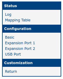
The web interface features a menu on the left side, which includes Status, Configuration, and Customization sections. The Status section provides Log and Mapping Table views, while the Configuration section includes options for basic Settings, Expansion Ports 1 and 2, and USB Port. The Customization section contains a Return option to navigate back to the router's main web configuration pages. The menu is shown in the figure below.
Configuration
Basic Settings
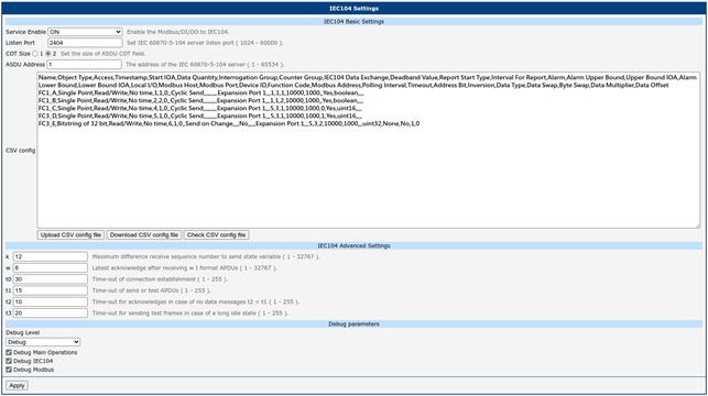
Basic configuration for this Router App is available on the Basic page under the Configuration menu. The configuration items are shown in the figure below and described in the table.
| Item | Description |
|---|---|
| Service Enable | Enable Modbus RTU/TCP to IEC 60870-5-104 functionality. |
| Listen Port | Set the IEC-104 server listen port. Range: 1024 – 60000 |
| COT Size | Set the size of the ASDU Cause of Transmission (COT) field. |
| ASDU Address | Address of the IEC 60870-5-104 server. Range: 1 – 65534 |
| CSV config | Upload, download, or check the CSV configuration file for correct rules. |
| k | Maximum difference between receive sequence number and send state variable. Range: 1 – 32767 |
| w | Latest acknowledge after receiving w I-format APDUs. Range: 1 – 32767 |
| t0 | Time-out for connection establishment. Range: 1 – 255 |
| t1 | Time-out for send or test APDUs. Range: 1 – 255 |
| t2 | Time-out for acknowledges in case of no data messages (t2 < t1). Range: 1 – 255 |
| t3 | Time-out for sending test frames in case of a long idle state. Range: 1 – 255 |
| Debug Level | Debug log level: Debug > Info > Error > None Category: • Main Operations • IEC104 • Modbus |
Settings items
CSV File
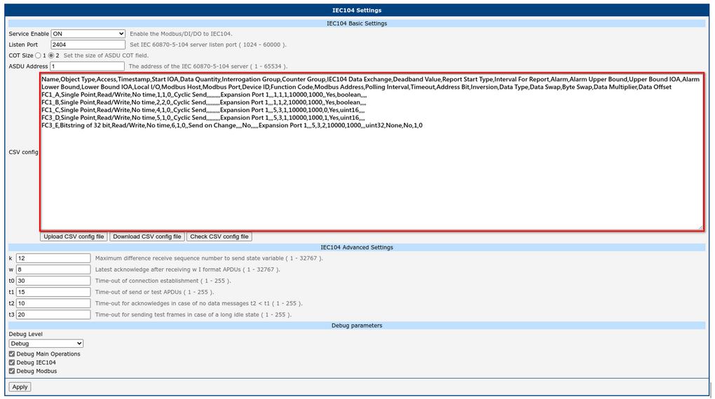
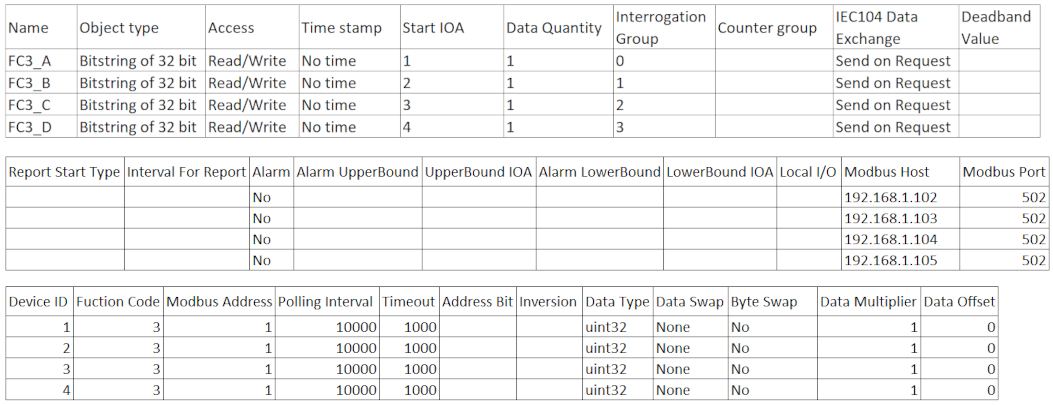
This Router App allows you to configure the mapping between Modbus TCP/RTU and IEC-104 using a CSV file. Fields in the CSV file are separated by commas.
The CSV file can be imported into the router on the Settings page in the Router App's web interface. After importing the CSV file and clicking Apply, the new mapping configuration takes effect immediately.
| Item | Description | Note |
|---|---|---|
| Name | User-defined description for the data point. | • The "Name" column cannot be empty. • The "Name" column cannot contain a comma. |
| Object Type | The data type defined in IEC60870-5 for each data point. Options: • Single Point • Double Point • Bitstring of 32 bit • Measured Normalized Value • Measured Scaled Value • Measured Short Floating Point Value • Integrated Totals • Clock Synchronization | • The "Object Type" column cannot be empty. • The "Object Type" column must be "Single Point" if the "Local I/O" column is DI or DO. |
| Access | The access right for the data point. Options: • Read-Only • Write-Only • Read/Write | • The "Access" column cannot be empty. • The "Access" column must be "Read Only" if the "Object Type" column is "Integrated Totals". • The "Access" column must be "Write Only" if the "Object Type" column is "Clock Synchronization". • The "Access" column must be "Read Only" if the "Local I/O" column is DI. • The "Access" column must be "Write Only|Read/Write" if the "Local I/O" column is DO. • The "Access" column cannot be "Write Only" if the "Address Bit" column is not empty. |
| Timestamp | Time stamp format for each data point. Options: • No time • CP24Time2a • CP56Time2a | • The "Timestamp" column cannot be empty. • The "Timestamp" column must be "No time" if the "Object Type" column is "Clock Synchronization". • The "Timestamp" column must be "CP56Time2a" if the "Local I/O" column is DI. • The "Timestamp" column must be "No time" if the "Local I/O" column is DO. |
| Start IOA | Unique Information Object Address (IOA) for the data point. | • The "Start IOA" column cannot be empty. • Check that the IOA range is unique and non-overlapping. |
| Data Quantity | Total number of data points. The total bit count must not exceed the maximum Modbus read limit of 2000 bits. | • The "Data Quantity" column cannot be empty. • The "Data Quantity" column must be "1" if the "Object Type" column is "Clock Synchronization". • The "Data Quantity" column must be "1" if the "Local I/O" column is DI or DO. • The "Data Quantity" column must be "1" if the "Address Bit" column is not empty. • The product of "Data Quantity" and the length of "Data Type" cannot exceed 2000. |
| Interrogation Group | Define the interrogation group (0 – 16, with 0 for General, 1 for Interrogation Group 1, etc.). | • The "Interrogation Group" column cannot be empty if the "Object Type" column is not "Integrated Totals" or "Clock Synchronization". • The "Interrogation Group" column must be empty if the "Object Type" column is "Integrated Totals" or "Clock Synchronization". |
| Counter Group | Define the counter group (1 – 5, with 5 for the general counter group). | • The "Counter Group" column cannot be empty if the "Object Type" column is "Integrated Totals". • The "Counter Group" column must be empty if the "Object Type" column is not "Integrated Totals". |
| IEC104 Data Exchange | Decides when data is sent to the IEC104 client. Options: • Send on Request — Data is only returned when asked. • Cyclic Send — Periodically sends data at the interval defined in the "Polling Interval" field. • Send on Change — Sends data only when the data changes. • Silence within Deadband — Sends data only when the data change exceeds the deadband range. | • The "IEC104 Data Exchange" column cannot be empty. • The "IEC104 Data Exchange" column cannot be "Silence within Deadband" if the "Object Type" column is "Single Point" or "Double Point". • The "IEC104 Data Exchange" column must be "Send on Request" if the "Object Type" column is "Clock Synchronization". |
| Deadband Value | If the difference between the current data and the previous deadband instance is less than this value, data is not sent to the IEC104 client; otherwise it is sent and updated. | • The "Deadband Value" column must be empty if the "Object Type" column is "Single Point", "Double Point" or "Clock Synchronization". • The "Deadband Value" column must be empty if the "Object Type" is not "Single Point", "Double Point" or "Clock Synchronization", and the "IEC104 Data Exchange" column is not "Silence within Deadband". • The "Deadband Value" column cannot be empty if the "Object Type" is not "Single Point", "Double Point" or "Clock Synchronization", and the "IEC104 Data Exchange" column is "Silence within Deadband". |
| Report Start Type | The freeze start type defines when the gateway begins sending M_IT messages or M_BO, M_MA, M_MB, M_MC messages that are still within the deadband value. Options: • Day • Hour • Minute • Not Used | • The "Report Start Type" column must be empty if the "Object Type" column is "Single Point", "Double Point" or "Clock Synchronization". • The "Report Start Type" column must be empty if the "Object Type" is not "Single Point", "Double Point" or "Clock Synchronization", and the "IEC104 Data Exchange" column is not "Silence within Deadband". • The "Report Start Type" column cannot be empty if the "Object Type" is not "Single Point", "Double Point" or "Clock Synchronization", and the "IEC104 Data Exchange" column is "Silence within Deadband". |
| Interval For Report | The time interval for spontaneous data reporting, in seconds. For example, if "Report Start Type" is "Hour" and "Interval For Report" is 900, data is reported every 15 minutes within one hour. | • The "Interval For Report" column must be empty if the "Object Type" column is "Single Point", "Double Point" or "Clock Synchronization". • The "Interval For Report" column must be empty if the "Object Type" is not "Single Point", "Double Point" or "Clock Synchronization", and the "IEC104 Data Exchange" column is not "Silence within Deadband". • The "Interval For Report" column cannot be empty if the "Object Type" is not "Single Point", "Double Point" or "Clock Synchronization", and the "IEC104 Data Exchange" column is "Silence within Deadband". • The "Interval For Report" value must be between 0 and 3600 if the "Report Start Type" column is "Hour". • The "Interval For Report" value must be between 0 and 60 if the "Report Start Type" column is "Minute". |
| Alarm | When data is in alarm mode and exceeds the upper or lower bound, an alarm (quality descriptor 0x01) is issued. If an upper or lower bound IOA is set, that Single Point IOA is set to 1. | • The "Alarm" column must be empty if the "Object Type" column is "Single Point", "Double Point" or "Clock Synchronization". • The "Alarm" column cannot be empty if the "Object Type" column is not "Single Point", "Double Point" or "Clock Synchronization". |
| Alarm Upper Bound | The upper bound of the alarm threshold. | • The "Alarm Upper Bound" column must be empty if the "Object Type" column is "Single Point", "Double Point" or "Clock Synchronization". • The "Alarm Upper Bound" column must be empty if the "Object Type" is not "Single Point", "Double Point" or "Clock Synchronization", and the "Alarm" column is "No". • The "Alarm Upper Bound" column cannot be empty if the "Object Type" is not "Single Point", "Double Point" or "Clock Synchronization", the "Alarm" column is "Yes", and the "Upper Bound IOA" column is not empty. • The "Alarm Upper Bound" column cannot be empty if the "Object Type" is not "Single Point", "Double Point" or "Clock Synchronization", the "Alarm" column is "Yes", the "Alarm Lower Bound" column is empty, and the "Lower Bound IOA" column is empty. |
| Upper Bound IOA | The upper bound alarm threshold. Binds a writable Single Point IOA to trigger an upper bound alarm. | • The "Upper Bound IOA" column must be empty if the "Object Type" column is "Single Point", "Double Point" or "Clock Synchronization". • The "Upper Bound IOA" column must be empty if the "Object Type" is not "Single Point", "Double Point" or "Clock Synchronization", and the "Alarm" column is "No". • The "Upper Bound IOA" column cannot be empty if the "Object Type" is not "Single Point", "Double Point" or "Clock Synchronization", the "Alarm" column is "Yes", and the "Alarm Upper Bound" column is not empty. • The "Upper Bound IOA" column cannot be empty if the "Object Type" is not "Single Point", "Double Point" or "Clock Synchronization", the "Alarm" column is "Yes", the "Alarm Lower Bound" column is empty, and the "Lower Bound IOA" column is empty. |
| Alarm Lower Bound | The lower bound of the alarm threshold. | • The "Alarm Lower Bound" column must be empty if the "Object Type" column is "Single Point", "Double Point" or "Clock Synchronization". • The "Alarm Lower Bound" column must be empty if the "Object Type" is not "Single Point", "Double Point" or "Clock Synchronization", and the "Alarm" column is "No". • The "Alarm Lower Bound" column cannot be empty if the "Object Type" is not "Single Point", "Double Point" or "Clock Synchronization", the "Alarm" column is "Yes", and the "Lower Bound IOA" column is not empty. • The "Alarm Lower Bound" column cannot be empty if the "Object Type" is not "Single Point", "Double Point" or "Clock Synchronization", the "Alarm" column is "Yes", the "Alarm Upper Bound" column is empty, and the "Upper Bound IOA" column is empty. |
| Lower Bound IOA | Binds a writable Single Point IOA to trigger a lower bound alarm. | • The "Lower Bound IOA" column must be empty if the "Object Type" column is "Single Point", "Double Point" or "Clock Synchronization". • The "Lower Bound IOA" column must be empty if the "Object Type" is not "Single Point", "Double Point" or "Clock Synchronization", and the "Alarm" column is "No". • The "Lower Bound IOA" column cannot be empty if the "Object Type" is not "Single Point", "Double Point" or "Clock Synchronization", the "Alarm" column is "Yes", and the "Alarm Lower Bound" column is not empty. • The "Lower Bound IOA" column cannot be empty if the "Object Type" is not "Single Point", "Double Point" or "Clock Synchronization", the "Alarm" column is "Yes", the "Alarm Upper Bound" column is empty, and the "Upper Bound IOA" column is empty. |
| Local I/O | The port on which the Modbus RTU connection is established, or that operates as digital input or digital output. If "Modbus Host" and "Modbus Port" contain an IP address and TCP port for Modbus/TCP, this field must be empty. | • The "Local I/O" column cannot be empty if the "Modbus Host" column is empty and the "Modbus Port" column is empty. • The "Local I/O" column must be empty if the "Modbus Host" column is not empty. • The "Local I/O" column must be empty if the "Modbus Port" column is not empty. |
| Modbus Host | The Modbus device IP address. | • The "Modbus Host" column cannot be empty if the "Local I/O" column is empty and the "Modbus Port" column is not empty. |
| Modbus Port | The TCP port number of the remote Modbus slave device. | • The "Modbus Port" column cannot be empty if the "Local I/O" column is empty and the "Modbus Host" column is not empty. |
| Device ID | The Modbus TCP/RTU slave ID. | • The "Device ID" column must be empty if the "Local I/O" column is DI or DO. • The "Device ID" column cannot be empty if the "Local I/O" column is "Expansion Port 1", "Expansion Port 2" or "USB Port". • The "Device ID" column cannot be empty if the "Modbus Host" column is not empty and the "Modbus Port" column is not empty. |
| Function Code | Modbus Function Code. Supported function codes: 1, 2, 3, 4, 5, 6, 15, 16 • 01: Read coils • 02: Read discrete inputs • 03: Read holding registers • 04: Read input register • 05: Write single coil • 06: Write single register • 15: Write multiple coils • 16: Write multiple registers | • The "Function Code" column must be empty if the "Local I/O" column is DI or DO. • The "Function Code" column cannot be empty if the "Local I/O" column is "Expansion Port 1", "Expansion Port 2" or "USB Port". • The "Function Code" column cannot be empty if the "Modbus Host" column is not empty and the "Modbus Port" column is not empty. • The "Function Code" column must be "16" if the "Object Type" column is "Clock Synchronization". • The "Function Code" column must be empty if the "Object Type" column is "Single Point", the "Access" column is "Read Only", the "Local I/O" column is "Expansion Port 1", "Expansion Port 2" or "USB Port", and the "Address Bit" column is not empty. • The "Function Code" column must be empty if the "Object Type" column is "Single Point", the "Access" column is "Read Only", the "Modbus Host" column is not empty, and the "Address Bit" column is not empty. • The "Function Code" column must be empty if the "Object Type" column is "Single Point", the "Access" column is "Read/Write", the "Local I/O" column is "Expansion Port 1", "Expansion Port 2" or "USB Port", and the "Address Bit" column is empty. • The "Function Code" column must be empty if the "Object Type" column is "Single Point", the "Access" column is "Read/Write", the "Local I/O" column is "Expansion Port 1", "Expansion Port 2" or "USB Port", the "Address Bit" column is not empty, and the "Data Type" column is "uint16" or "uint32". • The "Function Code" column must be empty if the "Object Type" column is "Single Point", the "Access" column is "Read/Write", the "Modbus Host" column is not empty, and the "Address Bit" column is empty. • The "Function Code" column must be empty if the "Object Type" column is "Single Point", the "Access" column is "Read/Write", the "Modbus Host" column is not empty, the "Address Bit" column is not empty, and the "Data Type" column is "uint16" or "uint32". • The "Function Code" column must be empty if the "Object Type" column is "Single Point", the "Access" column is "Write Only", and the "Address Bit" column is empty. • The "Function Code" column must be empty if the "Object Type" column is "Double Point" for any Access and Local I/O or Modbus Host combination. • The "Function Code" column must be empty if the "Object Type" column is not "Single Point", "Double Point" or "Clock Synchronization", and the "Access" column is "Read Only". • The "Function Code" column must be empty if the "Object Type" column is not "Single Point", "Double Point", "Integrated Totals" or "Clock Synchronization", and the "Access" column is "Read/Write" or "Write Only". |
| Modbus Address | The starting address for reading from or writing to the Modbus registry. | • The "Modbus Address" column must be empty if the "Local I/O" column is DI or DO. • The "Modbus Address" column cannot be empty if the "Local I/O" column is "Expansion Port 1", "Expansion Port 2" or "USB Port". • The "Modbus Address" column cannot be empty if the "Modbus Host" column is not empty and the "Modbus Port" column is not empty. |
| Polling Interval (ms) | Modbus polling interval in milliseconds. Range: 1 – 10000000 | • The "Polling Interval" column cannot be empty. |
| Timeout | The time span within which the Modbus server must return a Modbus response. Range: 100 – 10000 ms | • The "Timeout" column must be empty if the "Local I/O" column is DI or DO. • The "Timeout" column cannot be empty if the "Local I/O" column is "Expansion Port 1", "Expansion Port 2" or "USB Port". • The "Timeout" column cannot be empty if the "Modbus Host" column is not empty and the "Modbus Port" column is not empty. |
| Address Bit | The bit address within a uint16 or uint32 Data Type for a Single Point data point. | • The "Address Bit" column must be empty if the "Object Type" column is not "Single Point". • The "Address Bit" value must be between 0 – 15 if the "Data Type" column is "uint16". • The "Address Bit" value must be between 0 – 31 if the "Data Type" column is "uint32". |
| Inversion | Inverts the Single Point value. | • The "Inversion" column must be empty if the "Object Type" column is not "Single Point". • The "Inversion" column cannot be empty if the "Object Type" column is "Single Point". |
| Data Type | Modbus data type. Options: • boolean • int16 • uint16 • float16 • int32 • uint32 • float32 • int64 • uint64 • float64 | • The "Data Type" column cannot be empty. • The "Data Type" column must be "boolean" if the "Object Type" column is "Double Point". • The "Data Type" column cannot be "boolean" if the "Object Type" column is not "Single Point", "Double Point" or "Clock Synchronization". • The "Data Type" column must be "uint32" if the "Object Type" column is "Clock Synchronization". |
| Data Swap | The order in which bytes of the received/transmitted data are processed. Options: • None — Do not swap • Word — 0x1a2b → 0x2b1a • Double Word — 0x1a2b3c4d → 0x3c4d1a2b • Double Word - Frame — 0x1a2b3c4d → 0x4d3c2b1a • Quad Word — 0x1a2b3c4d5e6f7980 → 0x79805e6f3c4d1a2b | • The "Data Swap" column must be empty if the "Object Type" column is "Single Point" or "Double Point". • The "Data Swap" column cannot be empty if the "Object Type" column is not "Single Point" or "Double Point". • The "Data Swap" column must be empty if the "Data Type" column is "int16", "uint16" or "float16". • The "Data Swap" column cannot be empty if the "Data Type" column is "int32", "uint32" or "float32". |
| Byte Swap | Swaps the nibbles in each byte of the data. Options: • True — 0x1a2b → 0xa1b2; 0x1a2b3c4d → 0xa1b2c3d4 • False — No swap | • The "Byte Swap" column must be empty if the "Object Type" column is "Single Point" or "Double Point". • The "Byte Swap" column cannot be empty if the "Object Type" column is not "Single Point" or "Double Point". |
| Data Multiplier | The value used to multiply the data value. | • The "Data Multiplier" column must be empty if the "Object Type" column is "Single Point" or "Double Point". • The "Data Multiplier" column cannot be empty if the "Object Type" column is not "Single Point" or "Double Point". |
| Data Offset | The value used to add or subtract from the data value. | • The "Data Offset" column must be empty if the "Object Type" column is "Single Point" or "Double Point". • The "Data Offset" column cannot be empty if the "Object Type" column is not "Single Point" or "Double Point". |
CSV items
Data Swap vs. Byte Swap
The following table shows examples of different combinations of Data Swap and Byte Swap.
| Source Data from Modbus Slave | Data Swap | Byte Swap | Resulting Data |
|---|---|---|---|
| 0x1a2b | None | FALSE | 0x1a2b |
| 0x1a2b | None | TRUE | 0xa1b2 |
| 0x1a2b | Word | FALSE | 0x2b1a |
| 0x1a2b | Word | TRUE | 0xb2a1 |
| 0x1a2b3c4d | None | FALSE | 0x1a2b3c4d |
| 0x1a2b3c4d | None | TRUE | 0xa1b2c3d4 |
| 0x1a2b3c4d | Double Word | FALSE | 0x3c4d1a2b |
| 0x1a2b3c4d | Double Word | TRUE | 0xc3d4a1b2 |
| 0x1a2b3c4d | Double Word — Frame | FALSE | 0x4d3c2b1a |
| 0x1a2b3c4d | Double Word — Frame | TRUE | 0xd4c3b2a1 |
| 0x1a2b3c4d5e6f7890 | None | FALSE | 0x1a2b3c4d5e6f7890 |
| 0x1a2b3c4d5e6f7890 | None | TRUE | 0xa1b2c3d4e5f68709 |
| 0x1a2b3c4d5e6f7890 | Quad Word | FALSE | 0x78905e6f3c4d1a2b |
| 0x1a2b3c4d5e6f7890 | Quad Word | TRUE | 0x8709e5f6c3d4a1b2 |
Data & Byte Swap combinations
Integrated Total Behavior in IEC104 Data Exchange Modes
When the Object Type of IEC104 data is "Integrated Totals", the behavior for each "IEC104 Data Exchange" mode is as follows.
Send on Request:
- When FRZ of the received counter interrogation command (T101) is 0, the latest counter value is replied. (Integrated Totals Mode B)
- After FRZ of received T101 is 1, the value of IEC104 data is frozen.
- After receiving a T101 with FRZ as 1, and then receiving a T101 with FRZ as 0, the frozen value is replied and the counter value's frozen state is lifted. (Integrated Totals Mode C)
Cyclic Send:
- IEC104 data is sent periodically using the "Polling Interval" value as the time interval.
- Before any T101 is received, the value of IEC104 data is the latest counter value. (Integrated Totals Mode A)
- After FRZ of received T101 is 1, the value of IEC104 data is frozen.
- When FRZ of received T101 is 0, the frozen counter value is replied and the counter value's frozen state is lifted. (Integrated Totals Mode D)
Send on Change:
- Before any T101 is received, IEC104 data is sent whenever the counter value changes.
- After FRZ of received T101 is 1, IEC104 data is no longer sent because the value has been frozen.
- When FRZ of received T101 is 0, the frozen counter value is replied and the counter value's frozen state is lifted. After that, IEC104 data is sent whenever the counter value changes.
Silence within Deadband:
- The object follows the behavior of deadband.
- After FRZ of received T101 is 1, the value of IEC104 data is frozen.
- After FRZ of received T101 is 0, the frozen value is replied and the counter value's frozen state is lifted.
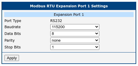
Modbus RTU Port Settings
Expansion Port 1 is for RS232, Expansion Port 2 is for RS485. The USB Port corresponds to device /dev/ttyUSB0.
| Item | Description |
|---|---|
| Baudrate | Modulation rate — the number of distinct symbol changes (signaling events) made to the transmission medium per second. |
| Data Bits | Number of data bits (7 or 8). |
| Parity | Parity setting: none, even, or odd. |
| Stop Bits | Number of stop bits (1 or 2). |
Modbus RTU items