Protocol ALPHA-MODBUS
Description
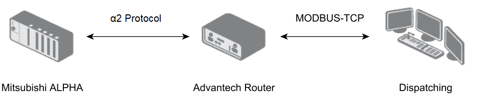
The ALPHA-MODBUS protocol is a binary, transparent serial protocol for communication with Mitsubishi ALPHA programmable logic controllers (PLCs). Between the Advantech router and the dispatching system, the MODBUS-TCP protocol is used. On the serial line between the router and the PLC, the proprietary α2 protocol is used. The router performs real-time, transparent conversion of data flowing in both directions.
In Client mode, the router communicates with the PLC at a configured interval. If no interval is configured, data is not sent regularly. Alarm flags are also detected within the configurable interval. Data is sent to the server either periodically according to the configured interval, or immediately when an alarm is detected. After the router reads and forwards the required data, the alarm flag is reset to inactive.
In Server mode, the router communicates only upon request from the dispatching system, and also supports writing values into the Mitsubishi ALPHA PLC.
Configuration
Introduction
Caution
Multiple programs cannot share access to the same serial interface. If a serial interface (on an expansion port or a USB ↔ serial converter) is enabled in the ALPHA-MODBUS Router App, it must not be enabled in any other Router App or in the system.
The application configuration is accessible from the Customization section under the Router Apps menu item.
For version 1.6.1 or earlier, a separate instance of the Router App is created for each serial interface during installation (e.g., ALPHA-MODBUS 1 and ALPHA-MODBUS 2).
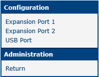
Newer versions install only a single instance of the Router App, which manages settings for all available interfaces. The application menu (shown in the figure below) displays only items corresponding to physically present hardware. For example, if the router does not have a second expansion port or a USB connector, those items will not be shown.
Newer versions also support the USB port, if available on the router, for connecting a serial converter.
Caution
If upgrading from version 1.6.1 or earlier to a newer version, the Expansion Port 2 interface must be manually reconfigured — the configuration is not transferred automatically.
Configuration Items
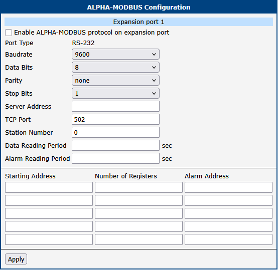
For each interface, the items shown in the figure below can be configured.
| Item | Description |
|---|---|
| Port Type | Indicates the detected type of the serial interface on the expansion port, or whether a USB ↔ serial converter is connected. |
| Baudrate | Communication speed in bits per second (bit/s). |
| Data Bits | Number of data bits: 7 or 8. |
| Parity | Parity setting: none, even, or odd. |
| Stop Bits | Number of stop bits: 1 or 2. |
| Server Address | IP address of the server (Client mode only). |
| TCP Port | TCP port number of the server or client. |
| Station Number | Address of the connected PLC. |
| Data Reading Period | Period for reading data (Client mode only). |
| Alarm Reading Period | Period for detecting alarms (Client mode only). |
| Starting Address | Starting address of the data area to send (Client mode only). |
| Number of Registers | Length of the data area to send (Client mode only). |
| Alarm Address | Address of the alarm register (Client mode only). |
Interface configuration items
Map of MODBUS/ALPHA Device Registers
Notes:
- More detailed information can be found in the Mitsubishi α2 Communication Manual and Mitsubishi α Software Manual.
- All items are 16-bit; the higher byte (MSB) is sent first.
| RefNum MODBUS | ALPHA Device | Can Write | Note |
|---|---|---|---|
| 1 | System Bit 1–16 | NO | — |
| 2 | System Bit 17–24 | NO | Bits 25–32 always 0 |
| 3 | Input Terminal 1–15 | YES | Bit 16 is always 0 |
| 4 | Reserve | YES | Not used, always 0 |
| 5 | External Input 1–4 | YES | Bits 5–16 always 0 |
| 6 | Output Terminal 1–9 | YES | Bits 10–16 always 0 |
| 7 | External Output 1–4 | YES | Bits 5–16 always 0 |
| 8 | Key Input 1–8 | YES | Bits 9–16 always 0 |
| 9 | Link Input 1–4 | YES | Bits 5–16 always 0 |
| 10 | Link Output 1–4 | YES | Bits 5–16 always 0 |
| 11 | Control Device 1–4 | YES | Bits 5–16 always 0 |
| 12–16 | Reserve | NO | Not used, always 0 |
| 17 | Analog In 1 | NO | — |
| 18 | Analog In 2 | NO | — |
| 19 | Analog In 3 | NO | — |
| 20 | Analog In 4 | NO | — |
| 21 | Analog In 5 | NO | — |
| 22 | Analog In 6 | NO | — |
| 23 | Analog In 7 | NO | — |
| 24 | Analog In 8 | NO | — |
| 25–256 | Reserve | NO | Not used, always 0 |
| 257 | System Bit 1–16 | NO | — |
| 258 | System Bit 17–24 | NO | Bits 25–32 always 0 |
| 259 | Input Terminal 1–8 | YES | Bits 9–16 always 0 |
| 260 | Reserve | YES | Not used, always 0 |
| 261 | External Input 1–4 | YES | Bits 5–16 always 0 |
| 262 | Output Terminal 1–6 | YES | Bits 7–16 always 0 |
| 263 | External Output 1–4 | YES | Bits 5–16 always 0 |
| 264 | Key Input 1–8 | YES | Bits 9–16 always 0 |
| 265 | Link Input 1–4 | YES | Bits 5–16 always 0 |
| 266 | Link Output 1–4 | YES | Bits 5–16 always 0 |
| 267 | Control Device 1–4 | YES | Bits 5–16 always 0 |
| 268–512 | Reserve | NO | Not used, always 0 |
| 513 | Communication Bit Device 1 | YES | — |
| 514 | Communication Bit Device 2 | YES | — |
| 515 | Communication Bit Device 3 | YES | — |
| 516–612 | Communication Bit Device 4 – Communication Bit Device 100 | YES | — |
| 613–1024 | Reserve | NO | Not used, always 0 |
| 1025 | Communication Word Device 1 | YES | — |
| 1026 | Communication Word Device 2 | YES | — |
| 1027 | Communication Word Device 3 | YES | — |
| 1028–1124 | Communication Word Device 4 – Communication Word Device 100 | YES | — |
| 1125–1536 | Reserve | NO | Not used, always 0 |
| 1537 | RTC — Year | YES | — |
| 1538 | RTC — Month | YES | — |
| 1539 | RTC — Day | YES | — |
| 1540 | RTC — Hour | YES | — |
| 1541 | RTC — Min | YES | — |
| 1542 | RTC — Sec | YES | — |
| 1543 | RTC — Adj | YES | — |
| 1544 | RTC — DoW | NO | — |
| 1545 | RTC — Status | NO | — |
| 1546–2048 | Reserve | NO | Not used, always 0 |
| 2049 | Run/Stop | YES | Write only — cannot be read. 1 = Run, 0 = Stop |
| 2050–8192 | Reserve | NO | Not used, always 0 |
| 8193–8216 | System Bit 1 – System Bit 24 | NO | — |
| 8217–8448 | Reserve | NO | Not used, always 0 |
| 8449–8463 | Input Terminal 1 – Input Terminal 15 | YES | — |
| 8464–8704 | Reserve | NO | Not used, always 0 |
| 8705–8708 | External Input 1 – External Input 4 | YES | — |
| 8709–8960 | Reserve | NO | Not used, always 0 |
| 8961–8969 | Output Terminal 1 – Output Terminal 9 | YES | — |
| 8970–9216 | Reserve | NO | Not used, always 0 |
| 9217–9220 | External Output 1 – External Output 4 | YES | — |
| 9221–9472 | Reserve | NO | Not used, always 0 |
| 9473–9480 | Key Input 1 – Key Input 8 | YES | — |
| 9481–9728 | Reserve | NO | Not used, always 0 |
| 9279–9282 | Link Input 1 – Link Input 4 | YES | — |
| 9283–9984 | Reserve | NO | Not used, always 0 |
| 9985–9988 | Link Output 1 – Link Output 4 | YES | — |
| 9989–10240 | Reserve | NO | Not used, always 0 |
| 10241–10244 | Control Device 1 – Control Device 4 | YES | — |
Map of MODBUS/ALPHA device registers