Operating Hours Counter
Caution
- This Router App has been tested on a router with firmware version 6.3.10. After updating the router firmware to a higher version, check whether a newer version of the Router App has also been released and update it accordingly for compatibility.
Tips
This Router App is not compatible with the v4 platform.
Description
The Operating Hours Counter Router App provides one resettable and one non-resettable time counter for each binary input on the router. It works with both the router's built-in binary inputs and the binary inputs on an expansion Advantech CNT card, if installed.
The counters are triggered by the state of the corresponding binary input — they run while the binary input is in the On state. Note that the logic and voltage levels may vary between different Advantech router models.
Current counter values for all inputs can be read from the router using the Modbus TCP protocol. The protocol can also be used to reset the resettable counters. For details about Modbus TCP communication, see the Modbus TCP Communication section.
Web Interface
Main Menu
The web interface of the Operating Hours Counter router app is accessible by clicking the Router App name on the Router Apps page of the router's web interface.
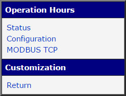
The main menu contains an Operation Hours section with Status and Configuration pages, as shown in the figure below. The Customization section contains only the Return item, which returns to the router's main web configuration interface.
Status
The status of all available time counters can be viewed on the Status page, as shown in the figure below. One line is displayed for each binary input, showing the current value of both the non-resettable (fixed) and resettable time counters. The time format is hhhhh:mm:ss (h = hours, m = minutes, s = seconds).

Configuration
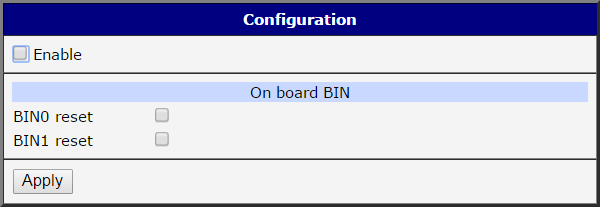
Router App activation and configuration are performed on the Configuration page, shown in the figure below. The Router App is activated by checking the Enable checkbox. Resettable counters can be reset by checking the corresponding BINx reset checkbox. Click Apply to save and apply the new configuration.
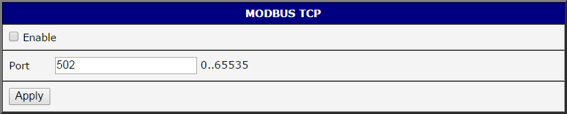
Before using Modbus TCP communication, the protocol must be enabled on the Modbus TCP configuration page by checking the Enable checkbox, as shown in the figure below. The default port is 502 and can be changed in the Port field. Click Apply to save and apply the new configuration.
Modbus TCP Communication
Address Mapping
Values of resettable counters are stored in Holding Registers and values of non-resettable counters are stored in Input Registers (Modbus terminology). Each counter occupies two Modbus registers with a total size of 4 bytes. Data are stored in big-endian format — the most significant byte is stored in the register with the lower address.
The router's built-in binary inputs (typically IN0 and IN1) are mapped first, followed by binary inputs on the expansion Advantech CNT card, if installed.
Input Registers — non-resettable counters:
| Counter No. | Register No. | Data Address | Access | Binary Input | Description |
|---|---|---|---|---|---|
| 1 | 30001 | 0x00 | R/- | BIN1 (IN0) | Two MSB bytes. |
| 1 | 30002 | 0x01 | R/- | BIN1 (IN0) | Two LSB bytes. |
| 2 | 30003 | 0x02 | R/- | BIN2 (IN1/CNTx) | Two MSB bytes. |
| 2 | 30004 | 0x03 | R/- | BIN2 (IN1/CNTx) | Two LSB bytes. |
| 3 | 30005 | 0x04 | R/- | BIN3 (CNTy) | Two MSB bytes. |
| 3 | 30006 | 0x05 | R/- | BIN3 (CNTy) | Two LSB bytes. |
| ... | ... | ... | ... | ... | ... |
Non-resettable counters address mapping
Holding Registers — resettable counters:
| Counter No. | Register No. | Data Address | Access | Binary Input | Description |
|---|---|---|---|---|---|
| 1 | 40001 | 0x00 | R/W | BIN1 (IN0) | Two MSB bytes. |
| 1 | 40002 | 0x01 | R/W | BIN1 (IN0) | Two LSB bytes. |
| 2 | 40003 | 0x02 | R/W | BIN2 (IN1/CNTx) | Two MSB bytes. |
| 2 | 40004 | 0x03 | R/W | BIN2 (IN1/CNTx) | Two LSB bytes. |
| 3 | 40005 | 0x04 | R/W | BIN3 (CNTy) | Two MSB bytes. |
| 3 | 40006 | 0x05 | R/W | BIN3 (CNTy) | Two LSB bytes. |
| ... | ... | ... | ... | ... | ... |
Resettable counters address mapping
Modbus Functions
Reading Counters
The following Modbus functions are used for reading registers containing counter values:
| Function Code | Description |
|---|---|
| 0x03 | Read Holding Register (resettable counters) |
| 0x04 | Read Input Register (non-resettable counters) |
Available Modbus functions for reading
Modbus functions are executed from a client acting as a Modbus master device. The exact syntax depends on the specific software implementation. All functions require at minimum two parameters: data address and data length. In this implementation, both parameters must be even numbers — otherwise an error is returned.
Resetting Counters
The following Modbus function is used for writing to registers of resettable counters:
| Function Code | Description |
|---|---|
| 0x10 | Write Holding Register (resettable counters) |
Available Modbus functions for writing
Writing any value to a resettable counter register resets it to zero, regardless of the value sent. It is not possible to set a resettable counter to a non-zero value.
Modbus Communication Examples
The examples below illustrate Modbus communication and data interpretation for the counter state shown in the figure below.
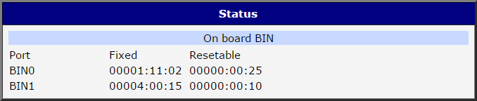
Querying value of counter no. 1
Resettable counter
Query: function 0x03, start address 0, data length 2
Returned: 0x00000019 → 0000:00:25
Non-resettable counter
Query: function 0x04, start address 0, data length 2
Returned: 0x000010A6 → 00001:11:02
Querying value of counter no. 2
Resettable counter
Query: function 0x03, start address 2, data length 2
Returned: 0x0000000A → 00:00:10
Non-resettable counter
Query: function 0x04, start address 2, data length 2
Returned: 0x0000384F → 00004:00:15
Resetting resettable counter no. 1
Query: function 0x10, start address 0, data length 2, sent data 0x00000000
Value set to: 0x00000000 → 00000:00:00
Resetting resettable counter no. 2
Query: function 0x10, start address 2, data length 2, sent data 0xFFFFFFFF
Value set to: 0x00000000 → 00000:00:00