Protocol MODBUS-RTUMAP
Description
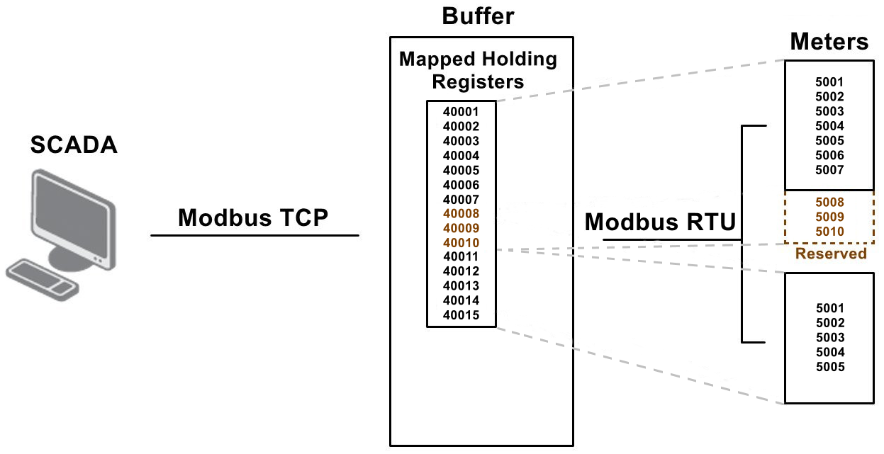
This Router App periodically reads data from Modbus RTU devices (meters) into a buffer. Each read value is mapped to a new virtual holding register, which is accessible via Modbus TCP. The mapped registers are arranged consecutively, with support for reserved gaps to ensure the mapping remains stable for future updates. The following figure illustrates this principle:
Writing to the mapped virtual holding registers is also supported. Written values are propagated back to the corresponding registers in the meters. Both single and multiple write functions can be used, but only for writable registers (coils and holding registers). An error is returned for read-only registers (discrete inputs and input registers).
Discrete registers (coils and discrete inputs) are not mapped 1:1, but as 16-bit groups. For example, when 20 coils are to be read from a meter, they are mapped to 2 holding registers. The first 16 coils are mapped to the first register, and the remaining 4 coils to the second register, leaving 12 bits unused.
Write-back is performed as a full block for the corresponding meter. For example, if a meter is configured to use 32 coils mapped to 2 holding registers, writing to either register via TCP will write all 32 coils back to the device via RTU.
If write-back via RTU fails (e.g., the device is powered off or a communication error occurs), the operation is retried continuously until it succeeds. While pending write values are waiting, new values are not read from the device. If a subsequent write request arrives before the previous one completes, only the most recent values are written back.
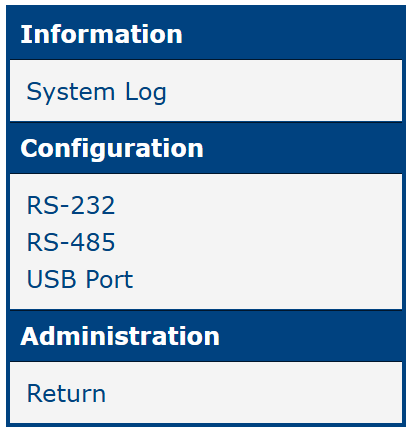
The Router App web interface is accessible by clicking the Router App name on the Router Apps page of the router's web interface. The left menu contains System Log in the Information section, expansion ports RS-232 & RS-485 and USB Port in the Configuration section, and Return in the Administration section, which switches back to the router's main interface. Items that are not available on the current hardware are not displayed.
Tips
The RTUMAP Router App uses zero-based addressing for registers. Register numbering starts from 0.
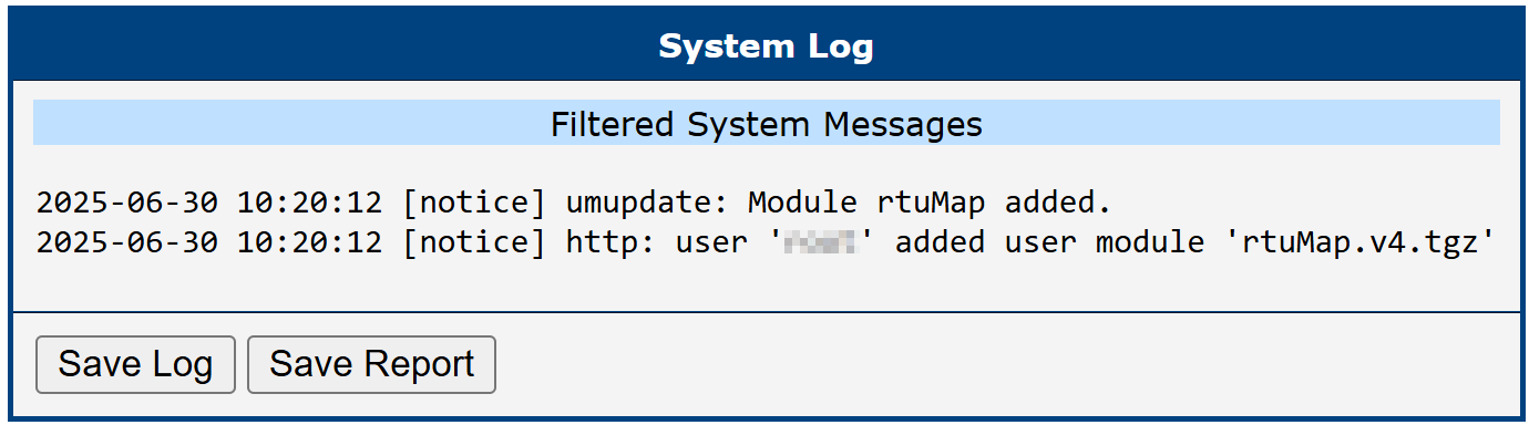
System Log
The System Log section provides access to runtime system events and diagnostic messages related to RTUMAP operation. This includes Modbus communication activity, error reports, and internal application status.
This section is intended primarily for monitoring and troubleshooting — it allows you to verify correct operation and identify issues such as failed communication with Modbus devices or configuration errors.
Two buttons are available at the bottom of the System Log view:
- Save Log — saves the full log content for review or archiving.
- Save Report — generates a summary report with key diagnostic data, useful for technical support or documentation.
Terminology Clarification
Standard Modbus terminology can sometimes be ambiguous. In this document, the following terms are used as described below:
- The standalone term Register refers to any of the following: Coil, Discrete Input, Holding Register, or Input Register.
- DO = Discrete Output = Coil
- DI = Discrete Input
- AO = Analog Output = Holding Register
- AI = Analog Input = Input Register
Configuration
Configuration is performed via the RS-232, RS-485, or USB Port forms for the respective expansion port. The configuration items are described in the table below.
| Item | Description |
|---|---|
| Enabled RTUMAP on X | Activates the RTUMAP Router App on the selected port: Expansion Port 1, Expansion Port 2, or the USB port. |
| Baudrate | Modulation rate — the number of distinct symbol changes per second on the transmission medium. |
| Data Bits | Number of data bits: 7 or 8. |
| Parity | Parity: none, even, or odd. |
| Stop Bits | Number of stop bits: 1 or 2. |
| Split Timeout | Time limit for reading each meter (in milliseconds). |
| Read Period | Period for reading the full data set from all meters into the buffer (in seconds). |
| TCP Port | TCP port number on which Modbus master requests are accepted. |
| Map Registers From | Starting address for mapped holding registers. A Modbus master (e.g., SCADA) reads and writes from/to addresses starting at this value. |
| Skipped Discrete Sends | Behavior when a Modbus TCP client reads a skipped discrete register (coil or discrete input): return an error or a default logical value (0 or 1). |
| Skipped Analog Sends | Behavior when a Modbus TCP client reads a skipped analog register (holding register or input register): return an error or a predefined default value. |
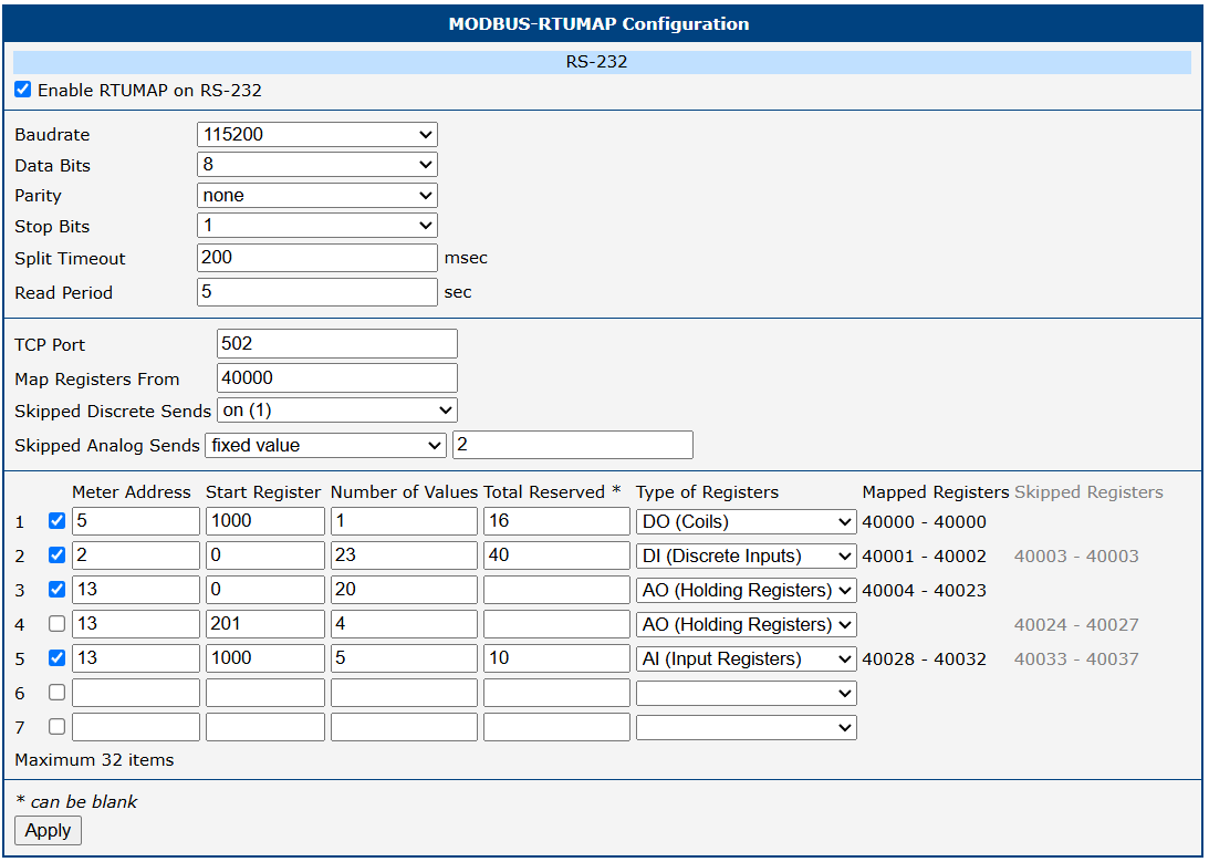
| Number | Row identifier — a unique number for each entry. |
| Checkbox | Enables or disables reading and writing for the related row. When disabled, the mapping addresses are still counted as reserved, preserving the mapping schema when re-enabled. |
| Meter Address | Modbus device address of the meter. |
| Start Register | Starting register on the Modbus device from which values are read. |
| Number of Values | Number of registers actively read and mapped from the Modbus device. |
| Total Reserved | Total number of registers reserved for reading. Allows future increases to Number of Values without changing the mapped address range. Only Number of Values registers are actively read; mapping is calculated as if Total Reserved registers were read. |
| Type of Registers | Determines which read/write functions are used, depending on the register type. |
| Mapped Registers | The range of mapped addresses calculated for this row, based on Map Registers From and Number of Values (e.g., 40000–40009). |
| Skipped Registers | Number of virtual holding register addresses to skip after this row's mapped range before the next row begins. Helps maintain a stable mapping layout across updates. |
Configuration items
Click Apply to apply all configuration changes.