Packet Splitter
Caution
- This Router App has been tested on a router with firmware version 6.3.10. After updating the router firmware to a higher version, check whether a newer version of the Router App has also been released and update it accordingly for compatibility.
Description
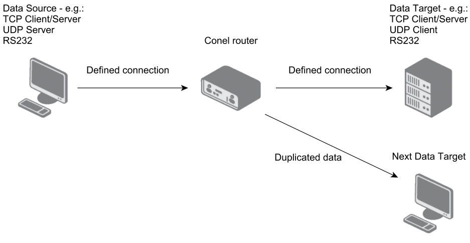
The Packet Splitter Router App allows duplicating a data flow to multiple targets (up to 7 different connections). It is suitable for applications where data flow duplication is needed — for example, data collection for statistical purposes, or forwarding data from a barcode reader to multiple destinations. The functional principle is illustrated in the figure below.
After uploading the Packet Splitter Router App, up to 5 TCP/UDP connections can be defined. If the router has RS-232 or RS-485/422 expansion ports installed, up to 2 additional serial connections can be configured (depending on the number of expansion ports). The number of defined connections does not equal the final number of duplicated data flows — for example, when a TCP server connection is defined, multiple clients can connect to it and all receive the data. Once connections are configured, one is set as the data source and the rest as data targets.
The Packet Splitter Router App is accessible in the router's web interface under Router Apps in the Customization section. Click on Packet Splitter to open its configuration.
Configuration
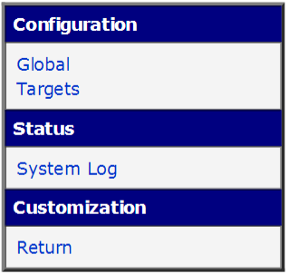
The Packet Splitter Router App menu is shown in the figure below. The Configuration section is split into two parts: Global, where the module is activated and connections are defined, and Targets, where one connection is set as the data source and the rest as targets. The Status section displays the system log. The Return item in the Customization section returns to the router's main web interface.
Global — Connection Configuration
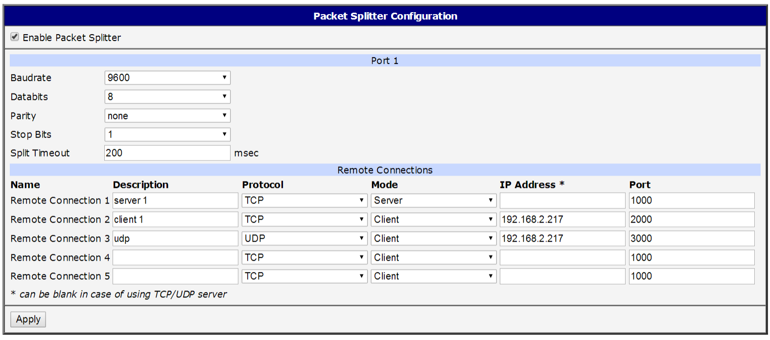
All Router App connections are defined in this section. The Router App is activated by checking the Enable Packet Splitter checkbox at the top of the page. All changes take effect after clicking the Apply button.
Caution
The Port 1 (and Port 2, if applicable) section is displayed only when a serial expansion port circuit board is connected to the router's main circuit board.
| Item | Description |
|---|---|
| Baudrate | Applied communication speed. |
| Data Bits | Number of data bits. |
| Parity | Control parity bit: • none — No parity. • even — Even parity. • odd — Odd parity. |
| Stop Bits | Number of stop bits. |
| Split Timeout | Message split threshold in milliseconds. If the gap between two received characters exceeds this value, all data received up to that point is compiled into a single message and forwarded. |
Serial port configuration items (Port 1 / Port 2)
The Remote Connections section allows defining up to 5 TCP or UDP connections:
| Item | Description |
|---|---|
| Description | Optional name for the connection, for easier identification in subsequent settings. |
| Protocol | Connection protocol: TCP or UDP. |
| Mode | Mode of the remote device: Server or Client. |
| IP Address | IP address of the remote device. May be left blank when using server mode. |
| Port | Port number for the communication (must be an available port). |
Remote connection configuration items
Targets — Target Configuration
After defining connections, their interconnections can be configured — one connection is selected as the data source and one or more connections are selected as data targets to which the source data is duplicated.
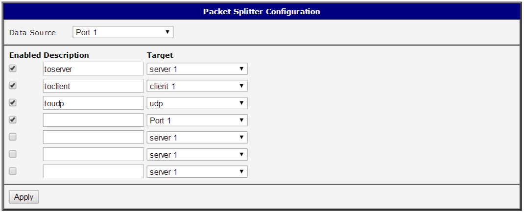
The Data Source selector at the top of the page is used to choose one of the defined connections as the data source. Up to 7 targets can be configured (5 TCP/UDP connections plus up to 2 serial connections when expansion ports are installed). Click Apply to save changes.
| Item | Description |
|---|---|
| Enabled | Activates forwarding of data from the Data Source to this target. |
| Description | Optional description or name for easier identification. |
| Target | Selects the target connection from the list of defined connections. |
Target configuration items
Caution
Some combinations of source and target configurations are invalid and will not work. Keep the principles of the selected protocols in mind — for example, with UDP, only a UDP server can be set as the data source, not a UDP client.
Tips
Configuration example — Duplicating serial port data to a TCP server and a TCP client: In the Global section, configure the serial port parameters and define two connections — a TCP server (IP address can be blank; set the listening port) and a TCP client (set the client's IP address and port). In the Targets section, set Port 1 as the Data Source, enable two targets, and assign them to the TCP server and TCP client connections. Both the remote TCP server and the remote TCP client then receive identical data from the serial port.
The Packet Splitter Router App behaves exactly as configured — it can send data to the same target twice, or send data back to the source, if that is how the Targets section is set up.
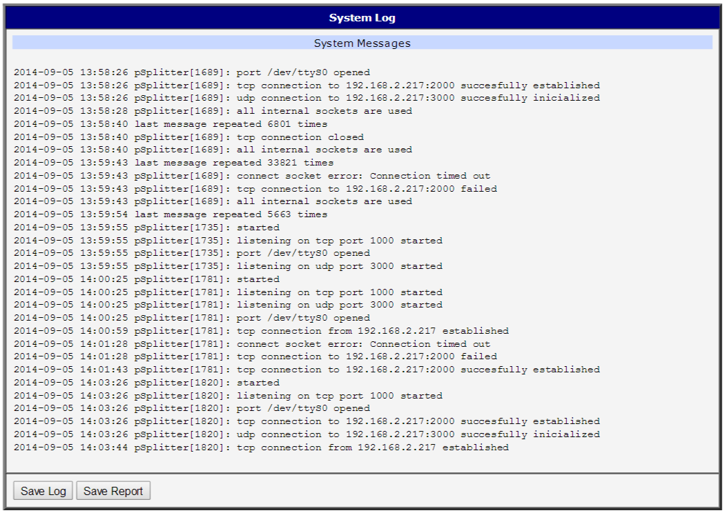
System Log
In case of connection problems, the system log can be viewed by clicking the System Log menu item. It displays detailed reports from all applications running on the router. Activity of the Packet Splitter Router App appears in rows starting with pSplitter. The log also shows whether connections were established successfully. Click the Save button to download the log to your computer.